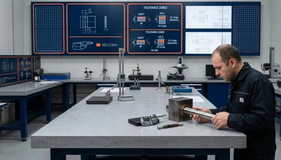
Understanding the limit fit and tolerance hole basis system is mandatory for establishing interchangeability in mass production across modern engineering workshops. In precision manufacturing, no two components can be produced to exact nominal dimensions; therefore, applying the limit fit and tolerance hole basis system allows ITI fitter trainees, design engineers, and quality inspectors to set permissible dimensional variations and clearance limits. This comprehensive guide breaks down the limit fit and tolerance hole basis system under National Council for Vocational Training (NCVT) Craftsmen Training Scheme (CTS) standards, detailing fundamental deviation symbols, tolerance grades, Bureau of Indian Standards (BIS) specifications, and workshop inspection procedures.
📌 Guide Navigation Index
1. Concept of Interchangeability & Basic Limit Terminology
Interchangeability refers to the production principle where any one component selected randomly from a batch of manufactured parts will assemble correctly with a mating component without requiring custom fitting or alteration. Applying the limit fit and tolerance hole basis system is the cornerstone of modern assembly lines, allowing parts produced in different factories to fit together seamlessly.
1.1 Basic Size vs Nominal Size
Basic Size: The exact theoretical dimension from which all upper and lower limit variations are calculated.
Nominal Size: The general commercial designation used to identify a component size (e.g., a 25 mm shaft).
1.2 Limits of Size
Because manufacturing machinery cannot achieve zero-defect mathematical perfection, engineers specify two permissible extreme sizes for every feature.
1.2.1 Maximum Limit of Size (Upper Limit)
The maximum permissible physical dimension of a part. For a hole, it is the largest allowable internal diameter; for a shaft, it is the largest allowable external diameter.
1.2.2 Minimum Limit of Size (Lower Limit)
The minimum permissible physical dimension of a part. For a hole, it is the smallest allowable internal diameter; for a shaft, it is the smallest allowable external diameter.
2. Fundamental Deviations and Tolerance Zone Classifications
Tolerance is the total permissible variation in a component’s dimension. It represents the arithmetic difference between the Upper Limit of Size and the Lower Limit of Size.
2.1 Unilateral vs Bilateral Tolerance Systems
Understanding how tolerances are distributed relative to the zero line determines how tools are ground and how fundamental deviation and tolerance zone limits are maintained.
2.1.1 Unilateral Tolerance
Tolerances allowed strictly on one side of the zero line (either entirely positive or entirely negative). Example: 25.00 (+0.02 / -0.00) mm.
2.1.2 Bilateral Tolerance
Tolerances allowed on both sides of the zero line simultaneously. Example: 25.00 (+0.02 / -0.02) mm.
2.2 Fundamental Deviation
The fundamental deviation defines the position of the tolerance zone relative to the zero line. It is the deviation chosen to locate the tolerance zone closest to the basic size line.
2.2.1 The Zero Line
A graphical reference line representing the exact basic size. Deviations above the zero line are positive (+), while deviations below are negative (-).
3. Engineering Fits (Clearance, Transition & Interference Fits)
A fit is the degree of tightness or looseness between two mating parts (a hole and a shaft) when assembled. Fits are classified into three major engineering categories based on the clearance fit transition fit interference fit difference.
3.1 Clearance Fit
A fit where the minimum allowable hole diameter is always larger than the maximum allowable shaft diameter. This ensures a permanent positive gap between the mating parts, allowing free movement or sliding action.
3.1.1 Sub-types of Clearance Fits
- Slide Fit (H7/g6): Used for precision guiding slides and machine tool spindles.
- Running Fit (H8/f7): Used for journal bearings operating at normal speeds with lubricant film.
- Loose Running Fit (H11/c11): Used for agricultural machinery and exposed linkages subject to thermal expansion.
3.2 Transition Fit
A fit where the tolerance zones of the hole and shaft overlap. Depending on the actual size of the manufactured components, a transition fit may yield either a slight clearance or a slight interference.
3.2.1 Typical Applications
- Push Fit (H7/k6): Used for gears held on shafts with keys.
- Force/Light Drive Fit (H7/n6): Used for precision locating dowel pins and shaft couplings.
3.3 Interference Fit
A fit where the maximum allowable hole diameter is always smaller than the minimum allowable shaft diameter. The shaft is larger than the hole, creating a permanent negative gap that requires force, hydraulic press, or thermal expansion (shrink fitting) to assemble.
3.3.1 Common Interference Fits
- Press Fit (H7/p6): Permanent assembly for bushings in cast iron housings.
- Shrink Fit (H7/s6): Heavy power transmission setup such as locomotive wheel rims over steel axles.
4. Hole Basis System vs Shaft Basis System Comparison
When implementing standard limits and fits in industrial manufacturing, engineers select either a hole basis or a shaft basis system to standardize tooling costs.
4.1 The Hole Basis System
In the limit fit and tolerance hole basis system, the basic size of the hole is kept constant while different fits are obtained by varying the dimensions of the mating shaft. The lower deviation of the hole is strictly zero, represented by the capital letter symbol H.
Before machining precise holes on a lathe, turners consult foundational guidelines on centre lathe machine parts and operations to ensure true spindle alignment.
4.2 The Shaft Basis System
In the shaft basis system, the basic size of the shaft is kept constant while different fits are obtained by varying the dimensions of the mating hole. The upper deviation of the shaft is strictly zero, represented by the small letter symbol h.
4.3 Comparative Technical Analysis
Comparing the hole basis system vs shaft basis system demonstrates why global industrial standards prefer the hole basis design:
5. BIS & ISO System of Limits and Fits Symbol Notations
The BIS system of limits and fits follows the International Organization for Standardization (ISO) system, using letter symbols and numbers to define tolerance zones.
5.1 Fundamental Deviation Letter Symbols
- Capital Letters (A to ZC): Represent internal dimensions (Holes). 28 fundamental deviations exist for holes. Capital ‘H’ denotes a hole whose lower deviation is zero.
- Small Letters (a to zc): Represent external dimensions (Shafts). 28 fundamental deviations exist for shafts. Small ‘h’ denotes a shaft whose upper deviation is zero.
5.2 Standard Grade of Tolerance (IT Grades)
The magnitude of the tolerance zone is designated by International Tolerance (IT) grades. There are 18 standard IT grades numbered from IT01, IT0, IT1 to IT16.
5.2.1 IT Grade Application Ranges
- IT01 to IT04: High-precision gauge manufacturing and master reference blocks.
- IT5 to IT11: General engineering machining cuts (turning, reaming, grinding, and drilling).
- IT12 to IT16: Coarse manufacturing processes such as casting, forging, and stamping.
5.2.2 Interpreting Fit Symbols (e.g., 25 H7/g6)
A fit symbol designated as 25 H7/g6 translates as:
- 25: Basic size in millimeters.
- H: Hole basis system (Lower deviation of hole = 0).
- 7: IT7 grade tolerance for the hole.
- g: Fundamental deviation position for the shaft (Clearance fit).
- 6: IT6 grade tolerance for the shaft.
6. Practical Mathematical Examples & Limit Calculations
Solving limit and fit problems is a major practical requirement in NCVT trade examinations. Plain-text mathematics is used below to demonstrate step-by-step calculations.
6.1 Numerical Problem Example 1: Clearance Fit
Calculate the limits of size, hole tolerance, shaft tolerance, and maximum/minimum clearance for the fit designated as 40 H7/g6 given:
- Basic Size = 40.00 mm
- Hole H7 limits = 40.000 mm to 40.025 mm
- Shaft g6 limits = 39.975 mm to 39.991 mm
6.1.1 Step-by-Step Mathematical Solution
- Upper Limit of Hole: 40.025 mm
- Lower Limit of Hole: 40.000 mm
- Hole Tolerance: 40.025 – 40.000 = 0.025 mm (25 microns)
- Upper Limit of Shaft: 39.991 mm
- Lower Limit of Shaft: 39.975 mm
- Shaft Tolerance: 39.991 – 39.975 = 0.016 mm (16 microns)
- Maximum Clearance: Upper Limit of Hole – Lower Limit of Shaft = 40.025 – 39.975 = 0.050 mm
- Minimum Clearance: Lower Limit of Hole – Upper Limit of Shaft = 40.000 – 39.991 = 0.009 mm
Before taking precise micrometer measurements for these tolerance calculations, machinists verify component edge deburring using suitable types of files used in fitter shop surface finishing operations.
7. Quality Inspection Gauges for Hole Basis Verification
In high-speed mass production, measuring individual component dimensions using micrometers is time-consuming. Inspection teams use limit gauges designed according to Taylor’s Principle.
7.1 GO and NO-GO Limit Gauges
- GO Gauge: Controls the Maximum Material Limit (MML). It must enter or pass over the component feature smoothly under its own weight.
- NO-GO Gauge: Controls the Minimum Material Limit (MML). It must not enter or pass over the component feature.
7.2 Plug Gauges for Internal Hole Verification
For checking holes under the limit fit and tolerance hole basis system, Inspectors use double-ended cylindrical plug gauges. The GO plug checks the lower limit of the hole, while the NO-GO plug checks the upper limit.
For a complete guide to plug gauges, ring gauges, and snap gauges used in precision fitting shops, read our comprehensive tutorial on types of gauges used in fitter shop inspection hubs.
8. NCVT, DGT & MSDE Exam Syllabus Integration
Under the Ministry of Skill Development and Entrepreneurship (MSDE) and Directorate General of Training (DGT) standards, limits, fits, and tolerances represent a critical module in the ITI Fitter and Turner trade theory syllabus.
8.1 NIMI Pattern Exam Weightage
Questions covering IT grades, fundamental deviation letters, clearance calculation problems, and Taylor’s Principle account for 10% to 14% of total marks in the NCVT AITT online Computer-Based Test (CBT).
8.1.1 Apprenticeship & Railway Recruitment Relevance
Candidates preparing for Indian Railway RRB ALP trade tests or Public Sector Unit (PSU) skill exams (BHEL, DRDO, SAIL) must master the limit fit and tolerance hole basis system to pass both written papers and practical bench fitting skill tests. Official syllabus frameworks can be accessed via the Bharat Skills Official Portal.
Verifying hole pitch tolerances after drilling requires combining limit gauges with accurate drilling machine types and operations setups, and precision measurement tools.
9. NIMI Pattern Mock Tests & Category Navigation
Master all technical questions on limits, fits, and tolerances for your upcoming NCVT AITT online Computer-Based Tests (CBT) across our main study categories:
10. Frequently Asked Questions (NCVT CBT Exam Focus)
Q1: Why is the hole basis system preferred over the shaft basis system in mass production?
Ans: The hole basis system is preferred because internal hole tools (drills, reamers, broaches) are expensive and fixed in size. It is much easier and cheaper to alter external shaft diameters to obtain various fits while keeping the hole size constant.
Q2: What is the fundamental deviation letter symbol for a hole basis system?
Ans: The capital letter symbol H represents the hole basis system, where the lower deviation of the hole is strictly zero.
Q3: What is the main difference between a clearance fit and an interference fit?
Ans: In a clearance fit, the minimum hole size is always larger than the maximum shaft size (positive gap). In an interference fit, the maximum hole size is always smaller than the minimum shaft size (negative gap).
Q4: How many standard IT grades of tolerance exist in the BIS system?
Ans: There are 18 standard IT tolerance grades in the BIS system, numbered from IT01, IT0, IT1 to IT16.
Q5: What does the fit notation 25 H7/g6 represent?
Ans: It represents a basic size of 25 mm under the hole basis system (H) with an IT7 grade hole tolerance mated with a shaft having fundamental deviation ‘g’ (clearance fit) and IT6 grade shaft tolerance.
🚀 Ace Your NCVT AITT Online Examinations!
Practice official NIMI pattern mock tests across Trade Theory, Workshop Calculation & Science, and Employability Skills on Info ITI.