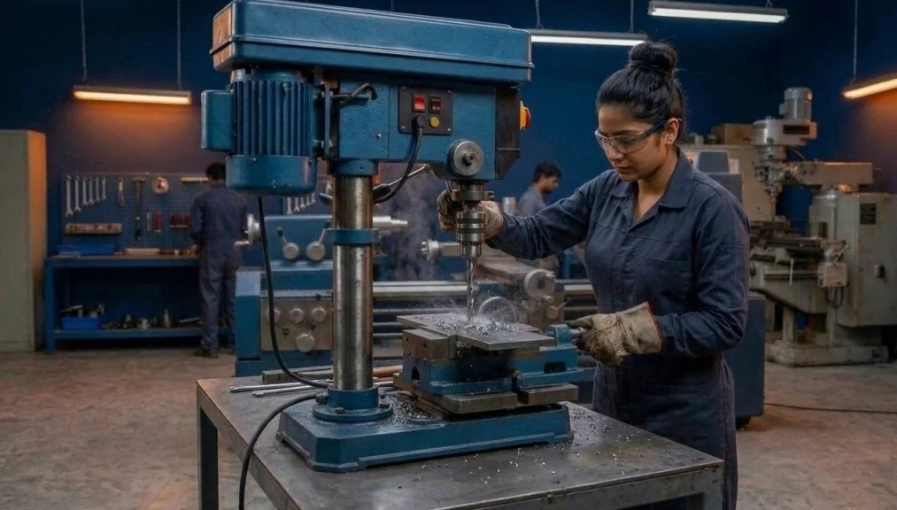
Mastering drilling machine types and operations is the essential foundation for achieving precision hole generation in any mechanical engineering fitting shop. Whether you are producing a simple clearance hole or a highly accurate reamed bore, understanding various drilling machine types and operations empowers machinists and ITI fitter trainees to select the correct tooling parameters and spindle speeds. This comprehensive selection guide details all essential drilling machine types and operations under National Council for Vocational Training (NCVT) Craftsmen Training Scheme (CTS) standards, covering machine structural classifications, twist drill bit point geometry, cutting fluid applications, and shop-floor safety protocols.
📌 Guide Navigation Index
1. Classifications & Construction of Drilling Machine Types and Operations
Drilling is a subtractive machining process that cuts a cylindrical hole into solid metals using a rotating end-cutting tool called a HIGH-SPEED STEEL (HSS) twist drill. Executing successful drilling machine types and operations requires recognizing which machine structural design best matches the size, weight, and batch quantity of the industrial workpiece.
In general machine shop practice, selecting proper structural equipment for drilling machine types and operations guarantees smooth tool entry and prevents drill breakage during deep-hole drilling cuts.
1.1 Portable Electric Drilling Machine
These are compact, hand-held motorized units used extensively for field maintenance, structural steel erecting, and assembly work. They handle drilling machine types and operations where heavy workpieces cannot be moved to fixed workshop equipment.
1.2 Sensitive Bench Drilling Machine
Mounted on a standard workbench for producing small-diameter holes (typically up to 12.5 mm). The feed is applied manually by a rack-and-pinion hand lever, allowing the operator to feel the cutting resistance and drill thrust (hence named “sensitive”).
Before placing a workpiece under a sensitive drill, fitters rely on accurate iti fitter marking tools and layout practice to establish deep 90-degree center punch marks that prevent the drill bit from wandering off-center.
1.3 Pillar (Column) Drilling Machine
A robust, floor-standing machine featuring a heavy cast iron base, vertical cylindrical column, adjustable swivel table, and stepped pulley head drive. Designed for medium-duty workshop hole production up to 50 mm diameter. It represents the most common setup for general drilling machine types and operations in ITI training institutes.
1.3.1 Base and Column Mechanics
The base is made of grey cast iron to absorb machine vibrations, while the column provides rigid alignment for the table and driving head.
1.4 Radial Drilling Machine
Designed for handling large, awkward castings that are difficult to align manually. Understanding the pillar drilling machine vs radial drill press difference is critical for heavy manufacturing:
2. Twist Drill Bit Anatomy & Point Angles for Different Metals
The standard consumable tool used during drilling machine types and operations is the straight shank or taper shank parallel twist drill. Knowing how to maintain these bits is a fundamental trade skill.
2.1 Anatomy of a Twist Drill Bit
- Flutes: Helical grooves running along the drill body to form cutting edges, channel cutting fluid, and evacuate metal chips upward.
- Land / Margin: A narrow cylindrical ridge running along the edge of the flutes to maintain true hole diameter and reduce side friction.
- Web: The central metal core of the drill body that increases in thickness toward the shank to provide torsional structural strength.
- Chisel Edge (Dead Center): The short horizontal line joining the two cutting lips at the extreme point of the drill.
2.1.1 Helix Angles
Standard twist drills feature a normal helix angle of 27.5 degrees (N-type) for mild steel. Slow helix (H-type) is used for brass, and quick helix (W-type) is used for aluminum.
2.2 Drill Bit Point Angles for Different Metals
Correctly selecting the drill bit point angle for different metals prevents point chipping, drill overheating, and rough surface finishes across various drilling machine types and operations:
- Standard Mild Steel & Cast Iron: 118 degrees point angle (Lip clearance angle: 8 to 12 degrees).
- Hard Steel & Stainless Alloys: 135 to 140 degrees point angle (Flatter point to resist heavy thrust forces without shattering).
- Soft Non-Ferrous Metals (Aluminum & Brass): 90 to 100 degrees point angle (Steeper point to prevent the bit from grabbing or digging in).
- Bakelite & Hard Plastics: 60 to 80 degrees point angle.
2.2.1 Lip Clearance Adjustment
Insufficient clearance angle causes the heel of the drill point to rub against the bottom of the hole, generating high friction without cutting metal.
Before drilling flat plates, machinists verify component edge flatness and stock thickness using appropriate types of files used in fitter shop surface preparation tasks.
3. Specialized Hole Finishing (Reaming, Counterboring & Countersinking)
Besides cutting primary cylindrical holes, executing diverse drilling machine types and operations includes secondary hole-finishing and fastener-seating techniques.
3.1 Reaming
Reaming is the process of sizing and finishing a previously drilled hole to high precision tolerance limits using a multi-tooth fluted reamer. A drilled hole is generally left 0.2 mm to 0.5 mm undersize to allow material for the reaming cut.
3.2 Counterboring vs Countersinking
Understanding the counterboring vs countersinking difference is a frequent practical exam question in NCVT trade theory related to drilling machine types and operations:
3.2.1 Counterboring Definition
Enlarging the end of a drilled hole cylindrically. It provides a flat shoulder to seat the head of a socket head cap screw flush with or below the metal surface.
3.2.2 Countersinking Definition
Beveling the end of a drilled hole cone-shaped (typically 75°, 80°, or 90°). This allows flat-head countersunk screws to seat perfectly flush with the surface.
3.2.3 Spot Facing Definition
Smoothing and squaring a flat circular seat around a hole on rough castings to provide a true bearing surface for bolt washers.
For generating axial center holes on long cylindrical shafts before mounting them between centers, operators transition smoothly between drilling setups and standard centre lathe machine parts and operations.
4. Cutting Speed, RPM, and Feed Calculation Formulas
Selecting proper cutting parameters prevents tool burn and ensures optimal chip removal during advanced drilling machine types and operations.
4.1 Cutting Speed Formula (V)
The cutting speed and feed formula for drilling calculates peripheral surface velocity in plain text mathematics:
V = (π × D × N) / 1000
- V: Cutting speed in meters per minute (m/min)
- D: Diameter of the drill bit in millimeters (mm)
- N: Spindle rotational speed in revolutions per minute (RPM)
- Spindle Speed Formula (N): N = (V × 1000) / (π × D)
4.1.1 Feed Rate Determination
Feed is the distance the drill bit advances into the workpiece per revolution (mm/rev). Smaller drills require fine feeds, while larger drills take coarse feeds.
5. Industrial Hole-Making Defect Troubleshooting Matrix
Quality inspection during drilling machine types and operations often reveals defects that stem from improper tool grinding or incorrect feed rates. The matrix below outlines root causes and fixes:
To verify hole depth and diameter accuracy after troubleshooting these defects, inspectors insert precision types of gauges used in fitter shop assemblies, such as GO/NO-GO plug gauges.
6. Work-Holding Accessories & Shop-Floor Safety Rules
Securing workpieces firmly during heavy drilling machine types and operations prevents the drill bit from grabbing the metal and spinning the job dangerously.
6.1 Work-Holding Devices
- Machine Vice: Holds square, rectangular, or flat jobs securely. Must be bolted to the T-slots of the machine table.
- V-Blocks with U-Clamps: Support round cylindrical shafts to prevent them from rolling during cross-hole drilling.
- Step Blocks & Clamping Plates: Clamps large irregular castings directly onto the machine table.
- Drill Jigs: Used in mass production to clamp the part and guide the drill bit continuously through hardened steel bushes without requiring manual layout marking.
6.2 Essential Drilling Safety Guidelines
- Never hold sheet metal or small workpieces by hand; always clamp them securely.
- Remove the chuck key from the drill chuck immediately after tightening the bit.
- Never wear loose clothing, neckties, or cotton gloves while operating rotating drill spindles.
- Always brush away metal chips; never use bare fingers or compressed air, which can blow sharp swarf into the eyes. For safety norms, visit the MSDE Official Portal.
Verifying hole pitch distances and counterbore depth tolerances requires combining exact precision measurement tools with standard drilling inspection protocols.
7. NCVT, MSDE & NIMI Pattern Syllabus Alignment
Under the Directorate General of Training (DGT) and Ministry of Skill Development and Entrepreneurship (MSDE) guidelines, understanding drilling machine construction forms a core part of the First-Year CTS trade theory curriculum.
7.1 NIMI Pattern Learning Outcomes
National Instructional Media Institute (NIMI) textbooks emphasize practical machine operations. Trainees must demonstrate independent competence in mounting drill bits, calculating cutting speeds, and grinding drill point angles to standard specifications.
7.1.1 AITT Computer-Based Test Weightage
In NCVT All India Trade Tests (AITT), questions on drill bit point angles, cutting speed formulas, and safety rules account for approximately 12% to 15% of the total Fitter Trade Theory marks.
8. Industrial Apprenticeship & Railway Recruitment Relevance
Mastering drilling machine types and operations is vital for candidates appearing for National Apprenticeship Certificate (NAC) exams and public sector job recruitments.
8.1 Indian Railways (RRB ALP & Technician Exam)
Indian Railway Recruitment Boards (RRB) frequently test candidates on practical workshop calculations, tool angles, and safety protocols in their Stage-2 CBT trade test papers.
8.2 Public Sector Units (PSU Recruitment)
Organizations such as ISRO, DRDO, BHEL, and IOCL conduct trade skill tests where candidates must perform precision drilling, tapping, and reaming tasks within tight tolerances.
9. NIMI Pattern Mock Tests & Category Navigation
Master all technical questions regarding drilling machine types and operations for your upcoming NCVT AITT online Computer-Based Tests (CBT) across our main study categories:
10. Frequently Asked Questions (NCVT CBT Exam Focus)
Q1: What is the standard point angle of a twist drill bit for drilling mild steel during general drilling machine types and operations?
Ans: The standard point angle for drilling mild steel is 118 degrees, with a lip clearance angle of 8 to 12 degrees.
Q2: What is the main structural advantage of a radial drilling machine over a pillar drill?
Ans: In a radial drilling machine, the drill head swivels 360 degrees and slides horizontally along a radial arm, moving over heavy stationary workpieces without requiring manual shifting of the job.
Q3: What is the difference between counterboring and countersinking during secondary drilling machine types and operations?
Ans: Counterboring enlarges a hole cylindrically to seat socket head caps, whereas countersinking bevels a hole conically to seat flat-head screws perfectly flush.
Q4: What is the cutting speed formula (V) for drill press machining?
Ans: Cutting speed is calculated as V = (π × D × N) / 1000, where V is cutting speed in m/min, D is drill bit diameter in mm, and N is spindle RPM.
Q5: Why is peck drilling used when machining deep cylindrical holes?
Ans: Peck drilling involves periodically retracting the drill bit to clear accumulated swarf chips from the helical flutes, preventing tool binding and drill breakage.
🚀 Ace Your NCVT AITT Online Examinations!
Practice official NIMI pattern mock tests across Trade Theory, Workshop Calculation & Science, and Employability Skills on Info ITI.