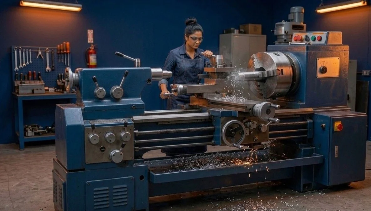
Known universally as the king of metalworking tools, the centre lathe machine represents the absolute core of industrial manufacturing and workshop metal removal. Mastering centre lathe machine parts and operations enables machinists, industrial turners, and ITI fitter trainees to perform straight turning, facing, taper turning, knurling, and thread cutting with exceptional precision. This comprehensive selection guide covers all essential centre lathe machine parts and operations under National Council for Vocational Training (NCVT) Craftsmen Training Scheme (CTS) standards, detailing structural machine specifications, drive mechanisms, work-holding accessories, taper turning trigonometric calculations, and cutting speed formulas.
📌 Guide Navigation Index
1. Structural Construction of Centre Lathe Machine Parts and Operations
The centre lathe operates on the fundamental principle of rotating a workpiece against a single-point cutting tool fed linearly along or across the axis of rotation. Executing successful centre lathe machine parts and operations begins with recognizing its core structural members, which must withstand heavy cutting forces while maintaining precise axial alignment.
In machine shop practice, selecting proper parameters for centre lathe machine parts and operations guarantees smooth surface finishes and prevents chatter vibrations during heavy roughing cuts on tough alloy steel bars.
1.1 The Lathe Bed
The bed forms the rigid foundation of the lathe machine, supporting the headstock, tailstock, and carriage assembly.
1.1.1 Material Composition
Lathe beds are cast from high-grade grey cast iron mixed with nickel and chromium. This provides high compressive strength, superior wear resistance, and high vibration-damping capacity. Bed guideways undergo induction hardening or flame hardening to prevent surface scoring.
1.1.2 Bed Ways Types
- Flat Ways: Provide large bearing surfaces suitable for heavy-duty industrial lathes.
- Inverted V-Ways: Provide accurate self-aligning guidance for the saddle and tailstock.
- Combination Ways: Feature both flat and V-guideways to balance precision guiding with structural load distribution.
1.2 Headstock Assembly
Mounted permanently on the left side of the bed ways, the headstock houses the main spindle, speed change gears, and driving cone pulleys.
1.2.1 Main Spindle
A hollow high-tensile alloy steel shaft supported by precision taper roller bearings. The spindle nose features an internal MORSE taper to receive live centers and an external thread or cam-lock flange to mount heavy chucks.
1.3 Tailstock (Loose Headstock)
Positioned on the right side of the bed ways, the tailstock slides along the inner guideways and can be clamped at any required distance.
1.3.1 Main Functions
- Supports long workpieces between centers using a dead center or revolving center.
- Holds cutting tools like twist drills, reamers, and taps in its internal MORSE taper barrel to perform axial hole machining operations.
- Can be offset laterally for turning long external shallow tapers.
2. Carriage Assembly & Feed Mechanisms in Centre Lathe Operations
The carriage spans the bed ways between the headstock and tailstock, providing support, guidance, and control for the single-point cutting tool during centre lathe machining and operations execution.
2.1 Structural Units of the Carriage
- Saddle: An H-shaped casting that slides along the bed guideways, supporting the cross-slide and apron.
- Cross-Slide: Mounted on top of the saddle, moving perpendicular to the lathe axis to control depth of cut or perform facing operations.
- Compound Rest: Mounted on the cross-slide, featuring a circular base graduated in degrees (swivel base) for swiveling to short taper angles.
- Tool Post: Mounted on top of the compound slide, clamping the tool bit firmly in position. Common types include single-screw tool posts, four-way square tool posts, and quick-change tool posts.
- Apron: Bolted to the front of the saddle, housing the gears, clutches, and half-nut lever that convert rotating feed shaft motion into manual or automatic tool movements.
2.2 Feed Mechanisms & Drives
Automatic tool movement requires precise synchronization with main spindle rotation. Understanding the tumbler gear mechanism in lathe carriage assemblies allows machinists to engage automatic feeds smoothly.
2.2.1 Lead Screw & Feed Shaft
- Lead Screw: A precision ACME thread screw used exclusively for thread-cutting operations when engaged via the apron half-nut lever.
- Feed Shaft: A long keyway-slotted shaft used to transmit automatic power feeds for general turning and facing operations.
2.2.2 Tumbler Gear Mechanism
Located inside the headstock gear train, the tumbler gear arrangement allows machinists to reverse the rotation direction of the lead screw and feed shaft without altering the main spindle rotation direction.
3. Work-Holding Accessories (Chucks, Faceplates & Steady Rests)
Choosing the correct work-holding device is vital when executing diverse centre lathe machine parts and operations tasks safely on the shop floor.
3.1 Three-Jaw Chuck vs Four-Jaw Chuck
Understanding the three-jaw vs four-jaw chuck difference is a fundamental requirement in NCVT trade examinations:
3.2 Additional Work-Holding Accessories
- Faceplate: A large circular cast iron plate with T-slots used to mount large, flat, or irregular workpieces that cannot be held in chucks.
- Driving Plate & Lathe Dog: Used to drive workpieces held between live and dead centers without slippage.
- Fixed Steady Rest: Clamped directly to the bed ways to support long, slender shafts and prevent sagging under cutting pressure.
- Follower Steady Rest: Mounted directly on the carriage saddle, moving along with the tool to prevent long thin shafts from springing away during continuous turning cuts.
For workpiece inspection guidelines following lathe turning, refer to our guide on types of gauges used in fitter shop inspection setups or check foundational layout steps in our tutorial on iti fitter marking tools and layout practice. Official trade patterns can be accessed via the Bharat Skills Official Portal.
4. Taper Turning Methods and Trigonometric Calculations
A taper is a gradual, uniform reduction in diameter along the length of a cylindrical workpiece. Mastering taper turning methods in lathe machine setups is essential for producing tool shanks, MORSE taper sockets, and bevel pinions during centre lathe machine parts and operations.
4.1 Standard Taper Formulas
The half-taper angle (alpha) or total taper angle (K) is calculated using the following plain text trigonometric formula:
tan(alpha) = (D – d) / (2 × L)
- D: Large diameter of taper in millimeters (mm)
- d: Small diameter of taper in millimeters (mm)
- L: Length of tapered section in millimeters (mm)
- alpha: Half-taper angle (degrees of compound rest swivel)
4.2 Taper Turning Methods Comparison
4.2.1 Form Tool Method
Uses a single-point tool ground with a wide cutting edge matching the desired taper angle. Limited to short tapers up to 15 mm in length (e.g., chamfering bolt heads).
4.2.2 Compound Rest Swivel Method
The compound rest is swiveled to the half-taper angle (alpha) and fed manually along the angular path. Ideal for turning steep, short internal and external tapers (e.g., lathe center points).
4.2.3 Tailstock Offset Method
The tailstock body is shifted laterally by an offset distance (S) from the headstock axis. Suitable for turning long, shallow external tapers between centers.
Offset (S) = [(D – d) × Total Length of Workpiece] / (2 × Length of Taper)
4.2.4 Taper Turning Attachment Method
Uses a specialized guide bar attached to the rear of the lathe bed to guide the cross-slide automatically. Enables automatic power feeding for both steep and shallow internal and external tapers without disturbing bed alignment.
5. Essential Machining Operations & Cutting Parameters
Executing precise centre lathe machine parts and operations requires establishing correct cutting speeds, feeds, and depths of cut tailored to the workpiece material.
5.1 Primary Lathe Machining Operations
- Facing: Machining the flat end face of a workpiece perpendicular to the axis of rotation using cross-slide movement.
- Straight Turning: Reducing the outer diameter along the axis of rotation using longitudinal carriage feed.
- Parting Off (Grooving): Cutting a narrow groove or completely severing a finished part from bar stock using a thin parting-off tool.
- Knurling: Pressing hardened steel knurling rollers against a rotating workpiece to produce a diamond or straight diamond-patterned serrated grip.
- Thread Cutting: Synchronizing spindle rotation with lead screw advancement via the apron half-nut to cut precise V-threads or ACME threads.
5.2 Cutting Speed and Feed Calculations
Understanding the cutting speed and feed calculation formula is essential for optimizing HIGH-SPEED STEEL (HSS) tool life and surface finish during centre lathe machine parts and operations:
V = (π × D × N) / 1000
- V: Cutting Speed in meters per minute (m/min)
- D: Diameter of the workpiece in millimeters (mm)
- N: Spindle rotational speed in revolutions per minute (RPM)
- Spindle Speed Formula (N): N = (V × 1000) / (π × D)
5.3 Maintenance & Workshop Safety Guidelines
- Never leave the chuck key inside the chuck socket; always remove it immediately after mounting workpieces.
- Wear OSHA-compliant PPE safety glasses and avoid wearing loose sleeves, rings, or neckties while operating rotating lathes.
- Apply lubricating oil to bed ways daily and clear chips using a brush; never use compressed air, which forces metal chips into sliding surfaces.
- For safety and administrative standards, consult directives on the MSDE Official Portal.
6. Industrial Lathe Troubleshooting & Defect Prevention Matrix
During practical shop-floor operations, machinists encounter operational defects stemming from incorrect tool angles, improper feed rates, or loose work holding. The matrix below outlines common troubleshooting procedures for centre lathe machine parts and operations:
7. Official Lathe Operation Blueprint & Formula Chart PDF
To assist ITI Fitter trainees, CITS instructors, and industrial turners during workshop practicals and CBT revision, our technical team has compiled a detailed reference chart. This downloadable PDF guide contains step-by-step compound rest swivel tables, tailstock offset formulas, cutting speed charts for mild steel vs cast iron, and lathe safety checklists under NIMI pattern standards.
Download Master Lathe Calculation & Formula Blueprint (PDF)
Get instant offline access to complete taper turning trigonometric tables, spindle RPM formulas, 3-jaw vs 4-jaw chuck setups, and NCVT practical exam reference sheets.
8. NIMI Pattern Mock Tests & Category Navigation
Master all technical questions on centre lathe machine parts and operations modules for your upcoming NCVT AITT online Computer-Based Tests (CBT) across our main study categories:
9. Frequently Asked Questions (NCVT CBT Exam Focus)
Q1: What material is primarily used to manufacture centre lathe beds?
Ans: Lathe beds are manufactured from high-grade grey cast iron alloyed with nickel and chromium due to its excellent compressive strength, wear resistance, and vibration-damping properties.
Q2: What is the main structural difference between a three-jaw chuck and a four-jaw chuck?
Ans: A three-jaw chuck features self-centering, scroll-driven jaws for round bar stock, whereas a four-jaw chuck has independently adjustable jaws for irregular workpieces.
Q3: Which taper turning method is best suited for turning steep, short tapers?
Ans: The compound rest swivel method is ideal for turning steep, short internal and external tapers by swiveling the rest to the half-taper angle (alpha).
Q4: What is the cutting speed formula (V) for lathe turning?
Ans: Cutting speed is calculated as V = (π × D × N) / 1000, where V is cutting speed in m/min, D is workpiece diameter in mm, and N is spindle speed in RPM.
Q5: Why is a follower steady rest mounted on the carriage saddle instead of the bed ways?
Ans: A follower steady rest mounts on the saddle so it moves along with the tool cut, continuously supporting thin shafts directly opposite the tool point to prevent workpiece springing.
10. Conclusion: Technical Mastery of Centre Lathe Machine Parts and Operations
The centre lathe remains an indispensable pillar of modern manufacturing, metal machining, and trade training. Developing a thorough understanding of centre lathe machine parts and operations allows machinists to transition smoothly between simple facing operations and intricate thread-cutting procedures. From calculating cutting speeds to selecting appropriate work-holding devices and setting up taper turning attachments, each technical element directly influences component accuracy and shop-floor productivity.
By mastering these fundamental operational principles and adhering strictly to workshop PPE safety standards, ITI students, CITS trainees, and mechanical technicians establish the practical competencies required to excel in NCVT All India Trade Tests (AITT) and secure rewarding technical careers in railway workshops, manufacturing plants, and defense production units.
🚀 Ace Your NCVT AITT Online Examinations!
Practice official NIMI pattern mock tests across Trade Theory, Workshop Calculation & Science, and Employability Skills on Info ITI.