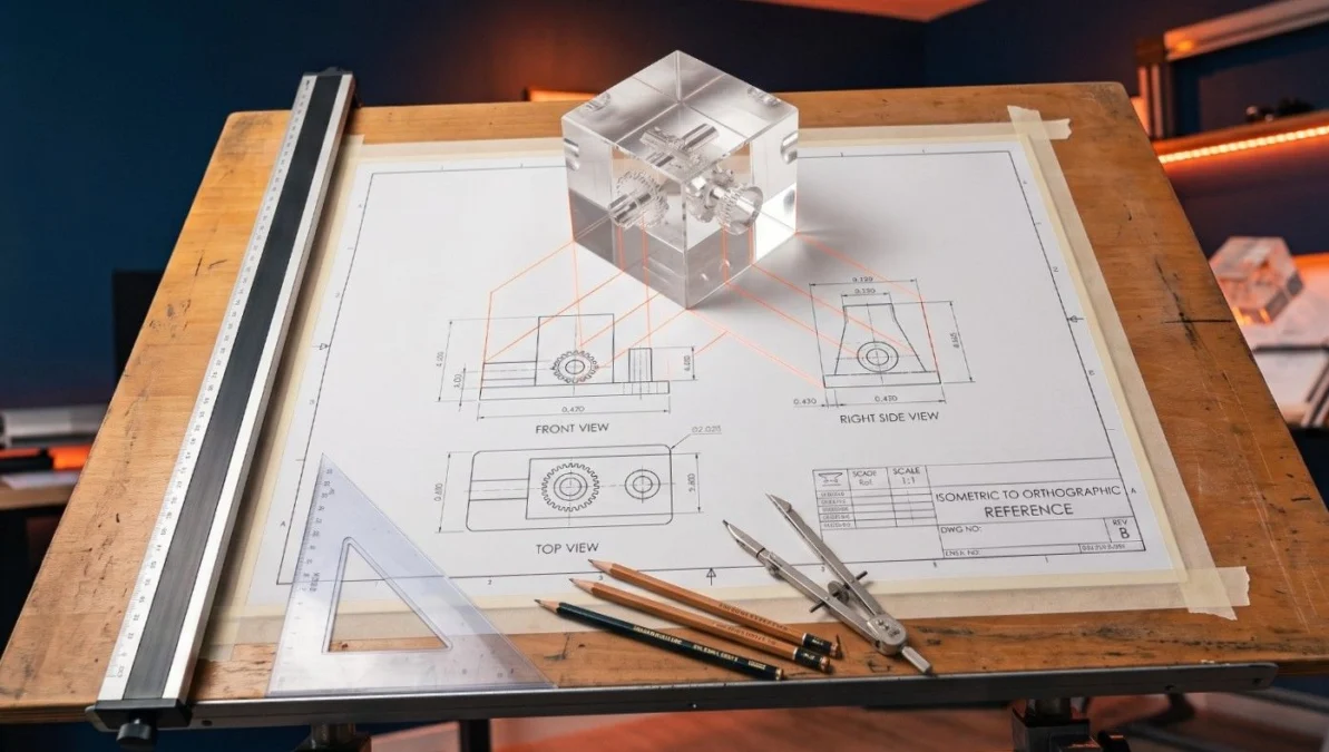
Understanding the isometric and orthographic projection difference is essential for interpreting industrial blueprints and converting 3D component concepts into 2D manufacturing drawings. Mastering the isometric and orthographic projection difference allows ITI fitter trainees, design draftsmen, and machining technicians to visualize component dimensions without visual misinterpretation. This comprehensive technical guide details the isometric and orthographic projection difference under National Council for Vocational Training (NCVT) Craftsmen Training Scheme (CTS) standards, covering Bureau of Indian Standards (BIS) rules, isometric scale math, viewing plane orientation, and shop-floor blueprint reading protocols.
📢 Share This Study Guide With Your Classmates & Friends!
📌 Guide Navigation Index
1. Fundamentals of Pictorial vs Multi-View Projections
Technical drawings serve as the precise communication link between design engineering and manufacturing workshops. When comparing the isometric and orthographic projection difference, the primary distinction lies in how many dimensions are displayed in a single view.
A pictorial projection shows all three principal dimensions (length, width, and height) in a single 3D view. In contrast, multi-view orthographic drawing breaks down an object into separate 2D views projected onto perpendicular planes.
1.1 Primary Purpose in Technical Manufacturing
- Isometric Drawings: Provide an immediate 3D visualization of component shapes for quick assembly comprehension.
- Orthographic Drawings: Provide exact 2D dimensions, hidden features, and manufacturing tolerances necessary for shop-floor machining.
1.1.1 Drafting Efficiency Standards
Machinists use orthographic views for precise dimensional measurement, while assembly technicians refer to isometric views to locate component relative positions.
2. Principles of Isometric Projection and Axis Angles
The term isometric originates from Greek words meaning equal measure. In an isometric drawing, the three principal space axes are inclined equally to the projection plane.
2.1 Isometric Axes, Lines, and Planes Setup
The three axes meeting at the origin point form 120-degree angles with each other. The vertical axis remains vertical, while the two horizontal axes are drawn inclined at 30 degrees to the horizontal baseline.
2.2.1 Isometric vs Non-Isometric Lines
Lines parallel to the isometric axes are called isometric lines, and measurements can be scaled along them directly. Lines not parallel to the axes are called non-isometric lines, and their true lengths cannot be measured directly.
Prior to constructing isometric views, trainees verify drafting tools using standards covered in our manual on engineering drawing instruments and lines.
3. Principles of Orthographic Projection and Viewing Planes
Orthographic projection projects parallel rays perpendicular to reference planes, creating true 2D view representations without perspective foreshortening.
3.1 The Three Principal Viewing Planes
- Vertical Plane (VP): Captures the Front View (Elevation), showing length and height.
- Horizontal Plane (HP): Captures the Top View (Plan), showing length and width.
- Profile Plane (PP): Captures the Side View (End View), showing width and height.
3.1.1 View Alignment Principles
The front view and top view are aligned vertically, sharing the same length dimensions. The front view and side view are aligned horizontally, sharing the same height dimensions.
To understand how orthographic views are arranged under Indian standards, consult our guide on first angle and third angle projection difference.
4. Comprehensive Isometric and Orthographic Projection Difference Matrix
Evaluating the isometric and orthographic projection difference helps clarify drafting selection across technical syllabus topics:
5. Isometric Scale Derivation Formula and Ratio Mathematics
When a cube is tilted so its body diagonal is perpendicular to the projection plane, all edges foreshorten equally.
5.1 Mathematical Derivation of Isometric Scale
The mathematical ratio between the isometric length and the true length is derived geometrically:
Isometric Length / True Length = Cosine 45° / Cosine 30° = (1 / √2) / (√3 / 2) = √(2 / 3) ≈ 0.8165
Thus, Isometric Length = 0.816 × True Length (or approximately 82% of actual length).
6. Step-by-Step Conversion: 3D Isometric View to 2D Orthographic Planes
Converting a 3D isometric drawing into 2D orthographic views requires systematic execution of 3d to 2d conversion rules:
6.1 Step-by-Step Drafting Procedure
- Step 1: Identify Viewing Direction: Determine the direction of Arrow X for the Front View, Arrow Y for the Top View, and Arrow Z for the Side View.
- Step 2: Calculate Overall Dimensions: Note the maximum length (L), height (H), and width (W) of the component.
- Step 3: Draw Reference Line (X-Y): Prepare layout blocks based on First Angle or Third Angle projection rules.
- Step 4: Draw Front View: Plot visible outlines using length and height measurements.
- Step 5: Project Top and Side Views: Extend thin projection lines (Type B) from the front view to locate features in top and side views.
- Step 6: Add Hidden Lines & Centerlines: Insert dashed lines for internal bores and chain lines for axis symmetry.
To verify dimensional tolerances on converted views, quality inspectors apply the limit fit and tolerance hole basis system.
7. Isometric View vs Isometric Projection Comparison
In technical drawing, understanding the distinction between an isometric view and an isometric projection is critical for exam success:
8. NCVT, DGT & MSDE Exam Syllabus Alignment
Under Directorate General of Training (DGT) and Ministry of Skill Development and Entrepreneurship (MSDE) curriculum guidelines, mastering 3D pictorial to 2D multi-view conversion is mandatory across all engineering trades.
8.1 NIMI Pattern Exam Weightage
Questions on isometric scale calculations, axis angles, and orthographic view conversions account for 15% to 18% of total marks in NCVT All India Trade Test (AITT) examinations. Official syllabus resources can be verified via the Bharat Skills Official Portal and the MSDE Official Portal.
Before sketching sheet metal component developments, trainees consult tools detailed in our sheet metal tools and joints manual and inspect parts using precision measurement tools.
🛠️
9. NIMI Pattern Mock Tests & Category Navigation
Master all technical questions regarding isometric and orthographic projections for upcoming NCVT AITT online Computer-Based Tests (CBT) across our study portals:
10. Frequently Asked Questions (NCVT CBT Exam Focus)
Q1: What is the angle between the two sloping horizontal axes in an isometric projection?
Ans: The two sloping horizontal axes are inclined at 30 degrees to the horizontal baseline, forming a 120-degree angle between each other.
Q2: What is the mathematical ratio of isometric scale to true scale?
Ans: The isometric scale ratio is √(2/3) or approximately 0.816 (81.6% of true length).
Q3: How many dimensions are shown in a single orthographic projection view?
Ans: Each individual orthographic projection view displays 2 dimensions (e.g., Front view shows Length and Height).
Q4: Why is an isometric view preferred over an isometric projection in workshop practice?
Ans: Because isometric views are drawn using true actual measurements (1:1 scale), allowing direct measurements using standard scales without conversion math.
Q5: How do circles appear in an isometric drawing?
Ans: Circles appear as foreshortened ellipses (isocircles) in isometric drawings.
🚀 Ace Your NCVT AITT Online Examinations!
Practice official NIMI pattern mock tests across Trade Theory, Workshop Calculation & Science, and Employability Skills on Info ITI.