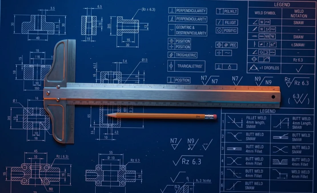
Understanding engineering drawing conventions and symbols is critical for correctly interpreting manufacturing blueprints and production layouts on the shop floor. Mastering engineering drawing conventions and symbols allows ITI fitter trainees, turners, machinists, and CITS instructors to decode material hatch patterns, surface texture finish symbols, and welding joint designations without ambiguity. This comprehensive technical guide covers engineering drawing conventions and symbols under National Council for Vocational Training (NCVT) Craftsmen Training Scheme (CTS) standards, detailing Bureau of Indian Standards (BIS IS: 696 and IS: 10714) specifications, machine element representations, structural fasteners, and practical blueprint reading protocols.
📢 Share This Study Guide With Your Classmates & Friends!
📌 Guide Navigation Index
Engineering Drawing Conventions and Symbols Overview
In technical workshops, creating full multi-view projections for complex machine parts requires excessive time and drawing space. Applying standardized engineering drawing conventions and symbols simplifies complex technical features into clear, universal graphical representations.
Bureau of Indian Standards (BIS IS: 696 and IS: 10714) governs all official engineering drawing conventions and symbols across Indian industries. Understanding engineering drawing conventions and symbols allows craftsmen to interpret structural materials, surface roughness grades, and permanent joints accurately.
Need for Standardization
- Saves Drafting Time: Replaces detailed repetitive geometric features with simplified graphical marks.
- Universal Clarity: Eliminates language barriers between design engineers and machine operators.
- Prevents Manufacturing Errors: Provides clear instructions for machining, welding, and heat treatment.
Material Hatching Conventions
When a component is shown in section, section lines (hatching) indicate the type of raw material used. Understanding material representation hatching conventions prevents material selection mistakes during fabrication.
Sectional Line Spacing
Section lines must be uniformly spaced depending on the size of the hatched area, typically varying between 1.5 mm and 3 mm apart.
Machine Element Conventions
Standard mechanical components like gears, springs, splined shafts, and bearings are represented using simplified machine element representation conventions.
Screw Threads and Fasteners
External screw threads are represented by continuous thick lines for the major diameter and continuous thin lines for the root diameter. Internal tapped holes use continuous thick lines for the drill hole and continuous thin lines for the thread crest.
Before sketching thread representations, trainees review thread geometry covered in our guide on fasteners types and applications.
Spur and Helical Gears
Gear tooth profiles are not drawn individually. The pitch cylinder is shown as a chain thin line (Type G), the tip cylinder as a continuous thick line (Type A), and the root cylinder as a continuous thin line (Type B).
Surface Texture Roughness Symbols
Surface finish dictates how machined parts function under friction and wear. Under surface texture roughness symbols, BIS is 696; surface quality is designated using a basic checkmark symbol.
Basic Checkmark Symbol Variations
- Basic Symbol: Open checkmark indicating surface finish without specifying machining method.
- Closed Symbol (Circle Added): Indicates that material removal by machining is strictly required.
- Bar Added Symbol: Indicates that material removal is strictly prohibited (as-cast or forged condition).
Roughness Grade Values (N1 to N12)
Surface roughness values (Ra in micrometers) are mapped to standard roughness grade numbers:
- N1 to N3 (Ra = 0.025 to 0.1 micrometers): Super-finished surfaces achieved by lapping or honing.
- N4 to N6 (Ra = 0.2 to 0.8 micrometers): High-precision ground and fine-turned bearing surfaces.
- N7 to N9 (Ra = 1.6 to 6.3 micrometers): Standard turned, milled, or shaped machine faces.
- N10 to N12 (Ra = 12.5 to 50 micrometers): Rough cast or flame-cut surfaces.
To verify dimensional limits on fine-turned surface grades, inspectors apply the limit fit and tolerance hole basis system.
Standard Welding Symbols Decoding
Welding symbols specify joint types, weld sizes, and field instructions on structural drawings. Decoding welding symbols on technical drawing blueprints ensures sound fabrication.
Components of a Welding Symbol
- Arrow Line: Points directly to the location of the weld joint.
- Reference Line: Horizontal line carrying weld shape symbols and dimensions.
- Basic Weld Symbol: Indicates joint geometry (Fillet, Square Butt, Single V-Butt, Spot weld).
- Tail: Placed at the end of the reference line for specifying welding processes or electrode specifications.
Arrow Side vs Other Side Rules
Symbols placed below the reference line indicate welds applied on the Arrow Side of the joint. Symbols placed above the reference line indicate welds applied on the Other Side of the joint.
🛠️
Practical Blueprint Reading Protocols
Interpreting engineering drawing conventions and symbols on workshop blueprints requires a systematic step-by-step reading methodology.
Blueprint Reading Sequence
- Step 1: Check Title Block: Review part name, drawing number, scale, projection symbol, and material specifications.
- Step 2: Read Main Views: Identify principal front, top, and side views to understand overall part geometry.
- Step 3: Decode Conventional Markings: Identify section hatching, knurling marks, square ends, and thread designations.
- Step 4: Inspect Roughness & Weld Signs: Check checkmark symbols for machining requirements and arrow lines for weld sizes.
Before taking physical dimensions from conventional drawings, trainees verify line types using our guide on engineering drawing instruments and lines and check overall scaling using our manual on types of scales in engineering drawing.
NCVT Exam Syllabus Alignment
Under Directorate General of Training (DGT) and Ministry of Skill Development and Entrepreneurship (MSDE) guidelines, mastering engineering drawing conventions and symbols is mandatory across all engineering trades.
NIMI Pattern Exam Weightage
Questions on conventional representations, surface finish marks, and welding symbols account for 12% to 15% of total marks in NCVT All India Trade Test (AITT) examinations. Official curriculum frameworks can be accessed on the Bharat Skills Official Portal and the MSDE Official Portal.
NIMI Pattern Mock Tests
Master all technical questions regarding engineering drawing conventions and symbols across our study portals:
Frequently Asked Questions
Q1: What angle is standard for material section hatching lines in engineering drawing?
Ans: Section hatching lines are drawn continuously thin at a 45-degree angle to the main outlines of the section.
Q2: Which surface roughness grade range corresponds to fine grinding or turning?
Ans: Roughness grades N4 to N6 (Ra = 0.2 to 0.8 micrometers) represent fine ground or turned surfaces.
Q3: What does a circle added to a basic surface texture checkmark symbol signify?
Ans: It signifies that material removal by machining is mandatory to achieve the specified surface finish.
Q4: Where is the welding symbol placed to indicate a weld on the Arrow Side?
Ans: The weld symbol is placed below the horizontal reference line to indicate a weld on the Arrow Side.
Q5: How are pitch circles represented in spur gear drawings?
Ans: Pitch circles are represented using chain thin lines (Type G lines).
🚀 Ace Your NCVT AITT Online Examinations!
Practice official NIMI pattern mock tests across Trade Theory, Workshop Calculation & Science, and Employability Skills on Info ITI.