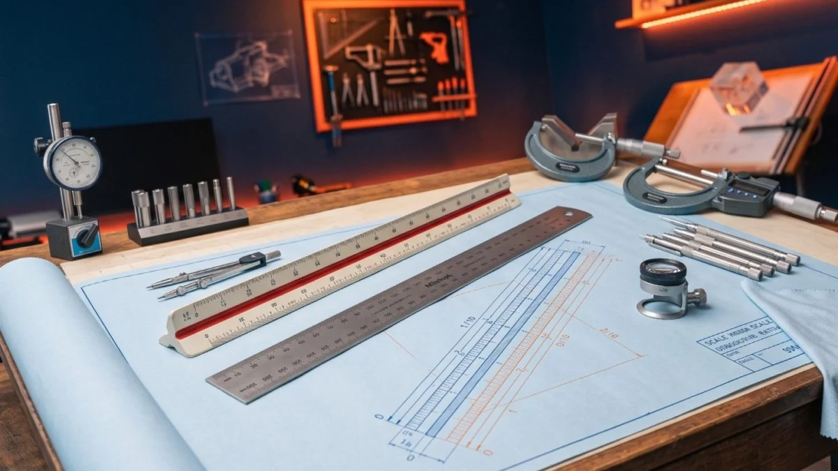
Understanding types of scales in engineering drawing is a foundational requirement for preparing accurate technical blueprints across mechanical workshops. Mastering types of scales in engineering drawing enables ITI fitter trainees, draftsmen, and CITS instructors to represent large buildings or miniature machine parts accurately on standard paper layouts. This comprehensive technical guide covers types of scales in engineering drawing under National Council for Vocational Training (NCVT) Craftsmen Training Scheme (CTS) standards, detailing Bureau of Indian Standards (BIS IS: 10711) rules, Representative Fraction (RF) calculations, reduced vs enlarged scales, plain scales, diagonal scales, and shop-floor blueprint reading principles.
📢 Share This Study Guide With Your Classmates & Friends!
📌 Guide Navigation Index
1. Types of Scales in Engineering Drawing Rules
In technical drafting, drawing components to their actual physical dimensions is not always practical. Studying types of scales in engineering drawing provides proportional methods to represent very large or microscopic objects on standard paper sizes.
A scale is defined as the ratio between the linear dimension of an element shown in a drawing and the actual physical dimension of the same element. Applying types of scales in engineering drawing ensures that technical proportions remain perfectly consistent during manufacturing.
1.1 Primary Objectives of Scaling
- Visual Clarity: Fits massive civil structures or tiny watch gears onto standardized drawing sheets.
- Proportional Accuracy: Maintains exact mathematical ratios across all projected views.
- Ease of Measurement: Allows technicians to read physical part sizes directly from blueprints.
2. Representative Fraction Calculation Math
Every scale drawing relies on a mathematical ratio known as the Representative Fraction (RF). Understanding RF calculations is a core part of mastering types of scales in engineering drawing.
2.1 Representative Fraction Formula
The Representative Fraction is calculated using the following basic equation:
Representative Fraction (RF) = Drawing Size of Object / Actual Size of Object
When calculating RF for types of scales in engineering drawing, both the numerator and denominator must be converted to the same unit of measurement before reducing the fraction.
2.2 Practical RF Case Study
If a 5-meter-long machine bed is represented on paper by a line measuring 10 centimeters, calculate the RF:
- Drawing Size = 10 cm
- Actual Size = 5 meters = 500 cm
- RF = 10 cm / 500 cm = 1 / 50 (or 1:50)
3. Full, Reduced, and Enlarged Scales
Under Bureau of Indian Standards (BIS IS: 10711) specifications, types of scales in engineering drawing are categorized into three major proportion groups.
4. Plain Scale Construction Principles
A plain scale consists of a line divided into suitable equal parts. It is one of the simplest types of scales in engineering drawing, used to measure up to two consecutive units.
4.1 Features of Plain Scales
- Measures two units like meters and decimeters, or centimeters and millimeters.
- Measures one unit and its fractional part (such as tenths).
- Features a zero mark placed one main division away from the left end, allowing sub-divisions to be read to the left.
4.2 Length of Scale Calculation
Before constructing plain scales, draftsmen calculate the physical length of scale (LOS) using the formula:
Length of Scale (LOS) = RF × Maximum Length to be Measured
Before constructing layout lines, students review tools covered in our guide on engineering drawing instruments and lines.
5. Diagonal Scale Construction Principles
When higher precision is required, draftsmen construct diagonal scales. Among the various types of scales in engineering drawing, diagonal scales are designed to measure three consecutive units.
5.1 Principle of Diagonal Division
Diagonal scales rely on the geometric principle of similar triangles. A short length is divided into small subdivisions by taking a diagonal line across a rectangular grid.
5.2 Applications of Diagonal Scales
- Measures three consecutive units like yards, feet, and inches, or meters, decimeters, and centimeters.
- Measures one main unit down to two decimal places (such as 3.47 meters).
When dimensioning orthographic projections constructed with diagonal scales, trainees apply rules detailed in our guide on first angle and third angle projection difference.
6. Vernier Scale Construction Principles
A Vernier scale consists of a main scale and a sliding Vernier scale. It is one of the most accurate types of scales in engineering drawing used in precision measuring instruments.
6.1 Forward vs Backward Vernier Scales
- Forward (Direct) Vernier: Vernier scale divisions are slightly smaller than main scale divisions ($VSD < MSD$). The scale reads in the same direction as the main scale.
- Backward (Retrograde) Vernier: Vernier scale divisions are slightly larger than main scale divisions ($VSD > MSD$). The scale reads in the opposite direction.
To understand how Vernier scales are integrated into precision shop-floor tools, review our manual on precision measurement tools.
7. NCVT Exam Syllabus Alignment
Under Directorate General of Training (DGT) guidelines, mastering types of scales in engineering drawing is mandatory across all ITI engineering trades under the Craftsmen Training Scheme (CTS).
7.1 NIMI Exam Weightage
Questions covering Representative Fraction calculations, scale types, and diagonal scale reading account for 10% to 14% of total marks in NCVT All India Trade Test (AITT) Computer-Based Tests (CBT). Official curriculum resources can be reviewed on the Bharat Skills Official Portal and the MSDE Official Portal.
Before dimensioning sheet metal layouts constructed with reduced scales, students consult sheet metal tools and joints practical guides.
🛠️
8. NIMI Pattern Mock Tests
Master all technical questions regarding types of scales in engineering drawing for upcoming NCVT AITT online Computer-Based Tests (CBT) across our study portals:
9. Frequently Asked Questions
Q1: What is Representative Fraction (RF) in types of scales in engineering drawing?
Ans: Representative Fraction (RF) is the ratio of the drawing size of an object to its actual physical size, expressed in identical units.
Q2: Which scale ratio represents a Full Size Scale under BIS IS: 10711?
Ans: A 1:1 ratio represents a Full Size Scale, where the drawing size equals the actual size.
Q3: How many consecutive units can a diagonal scale measure?
Ans: A diagonal scale can measure up to three consecutive units (such as meters, decimeters, and centimeters).
Q4: What is an Enlarged Scale used for in technical drawing?
Ans: An Enlarged Scale (such as 2:1, 5:1, or 10:1) is used to draw very small components like watch gears or electronic chips in a larger visible size.
Q5: How is the Length of Scale (LOS) calculated?
Ans: Length of Scale (LOS) is calculated by multiplying the Representative Fraction (RF) by the maximum length to be measured (LOS = RF × Maximum Length).
🚀 Ace Your NCVT AITT Online Examinations!
Practice official NIMI pattern mock tests across Trade Theory, Workshop Calculation & Science, and Employability Skills on Info ITI.