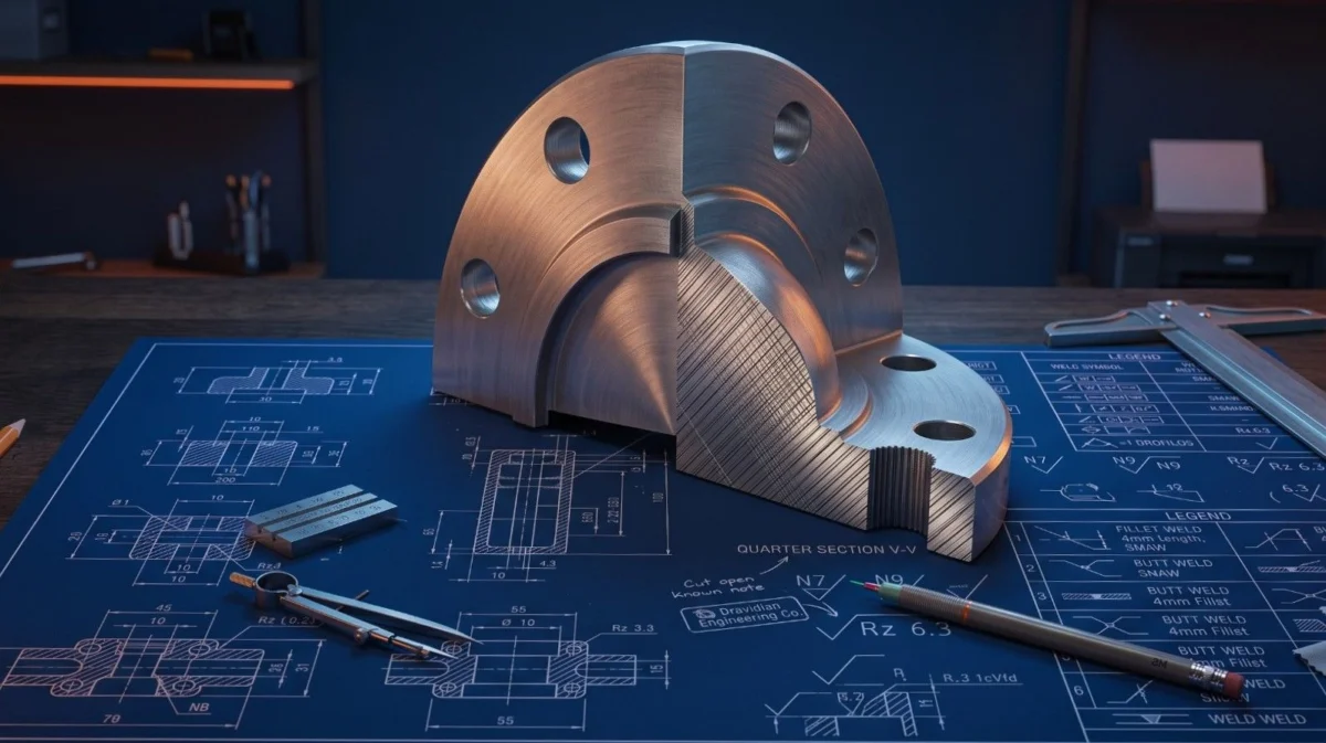
Understanding sectional views and cutting planes in engineering drawing is essential for revealing hidden internal features of complex machine components without confusing hidden lines. Mastering sectional views and cutting planes in engineering drawing allows ITI fitter trainees, turners, machinists, and CITS instructors to interpret internal bores, counterbores, and rib assemblies accurately on production blueprints. This comprehensive technical guide covers sectional views and cutting planes in engineering drawing under National Council for Vocational Training (NCVT) Craftsmen Training Scheme (CTS) standards, detailing Bureau of Indian Standards (BIS IS: 10714) rules, cutting plane line conventions, hatching standards, and non-hatched machine element rules.
📢 Share This Study Guide With Your Classmates & Friends!
📌 Guide Navigation Index
Sectional Views and Cutting Planes Overview
When an engineering object contains complex internal bores, keyways, or stepped chambers, standard orthographic views rely heavily on dashed hidden lines. Excessive hidden lines make drawings difficult to read and increase the risk of machining errors.
Applying sectional views and cutting planes in engineering drawing solves this problem by imagining a cutting plane passing through the object. Removing the front portion reveals solid internal structures as visible outlines.
Purpose of Sectioning
- Internal Clarity: Replaces overlapping hidden lines with clear solid outlines.
- Accurate Dimensioning: Allows direct dimensioning to internal bores and counterbores.
- Material Identification: Uses standardized section hatching to indicate raw material types.
Cutting Plane Line Specifications
A cutting plane indicates the exact path where the imaginary cut passes through the component. Under Bureau of Indian Standards (BIS IS: 10714), the cutting plane line type h bis is 10714 is designated as a Type H line.
Type H Line Geometry
A Type H line is a chain thin line (long dash, dot) that is drawn thick at both ends and at changes of direction.
- End Thickness: 0.5 mm thick continuous lines at extremities.
- Middle Thickness: 0.25 mm chain thin line through the interior body.
- Direction Arrows: Placed at 90 degrees to the cutting plane at both ends, pointing in the direction of view.
- Identification Letters: Capital letters (such as A-A, B-B) placed adjacent to direction arrows.
Types of Sectional Views Classification
Depending on how much of the object is cut and the path of the cutting plane, several types of sectional views in technical drawing are used across industrial manufacturing.
Full Section vs Half Section Difference
Evaluating the full section vs half section difference shows that full sections cut the entire object into two halves, making them ideal for non-symmetrical parts. Half sections remove only one quarter of symmetrical objects, preserving both internal and external visual details simultaneously.
Hatching Rules and Non-Hatched Parts
Section lines (hatching) indicate solid material cut by the cutting plane. Following standard hatching rules for ribs, webs, and fasteners is essential to avoid false visual impressions.
General Hatching Rules
- Line Type & Angle: Continuous thin lines (Type B) drawn at a 45-degree angle to principal outlines.
- Line Spacing: Uniformly spaced between 1.5 mm and 3.0 mm depending on view area size.
- Adjacent Parts: Hatching angles are drawn in opposite directions (45 degrees and 135 degrees) for adjacent assembled components.
Non-Hatched Machine Elements Rule
Certain solid standard parts are never hatched longitudinally when a cutting plane passes along their axis:
- Fasteners: Bolts, nuts, screws, studs, rivets, and washers.
- Shafts & Pins: Solid shafts, spindles, keys, cotters, dowel pins, and taper pins.
- Thin Structural Features: Ribs, webs, gear teeth, and spokes of wheels.
Before sketching thread section lines, trainees review fastener conventions covered in our guide on fasteners types and applications.
Practical Blueprint Reading Protocols
Reading sectional views and cutting planes in engineering drawing on workshop blueprints requires systematic execution:
Step-by-Step Blueprint Section Reading
- Step 1: Locate Cutting Plane Line: Find the Type H line with direction arrows and identification letters (e.g., A-A).
- Step 2: Determine Viewing Direction: Observe the arrow orientation to understand which half of the object is being viewed.
- Step 3: Match Sectional View: Locate the view labeled Section A-A on the blueprint.
- Step 4: Analyze Solid vs Bores: Hatched areas indicate solid metal cut by the plane; unhatched internal areas indicate open bores or channels.
To verify dimensional limits on sectioned internal bores, inspectors apply the limit fit and tolerance hole basis system.
🛠️
NCVT Exam Syllabus Alignment
Under Directorate General of Training (DGT) and Ministry of Skill Development and Entrepreneurship (MSDE) guidelines, mastering sectional views and cutting planes in engineering drawing is mandatory across all ITI engineering trades under the Craftsmen Training Scheme (CTS).
NIMI Pattern Exam Weightage
Questions on cutting plane line identification, hatching rules, and non-hatched elements account for 12% to 16% of total marks in NCVT All India Trade Test (AITT) examinations. Official curriculum frameworks can be accessed on the Bharat Skills Official Portal and the MSDE Official Portal.
Before dimensioning sectioned views, trainees verify line styles using our guide on engineering drawing instruments and lines and conventional marks using our manual on engineering drawing conventions and symbols.
NIMI Pattern Mock Tests
Master all technical questions regarding sectional views and cutting planes in engineering drawing across our study portals:
Frequently Asked Questions
Q1: What type of line is used to represent a cutting plane under BIS IS: 10714?
Ans: A Type H line (chain thin line, thick at both ends and at changes of direction) is used to represent a cutting plane.
Q2: Why are solid shafts and bolts left unhatched in sectional drawings?
Ans: Standard solid parts like shafts, bolts, nuts, and pins are left unhatched longitudinally to prevent visual clutter and maintain drawing readability.
Q3: How much of an object is removed in a half section view?
Ans: In a half section view, one quarter of the object is imagined to be removed, showing half internal and half external features.
Q4: What angle is standard for drawing section hatching lines?
Ans: Section hatching lines are drawn at a 45-degree angle to the principal outlines of the section.
Q5: When is an offset section used instead of a full section?
Ans: An offset section is used when internal features (like holes or slots) do not lie in a straight line, requiring the cutting plane to bend at 90-degree angles.
🚀 Ace Your NCVT AITT Online Examinations!
Practice official NIMI pattern mock tests across Trade Theory, Workshop Calculation & Science, and Employability Skills on Info ITI.