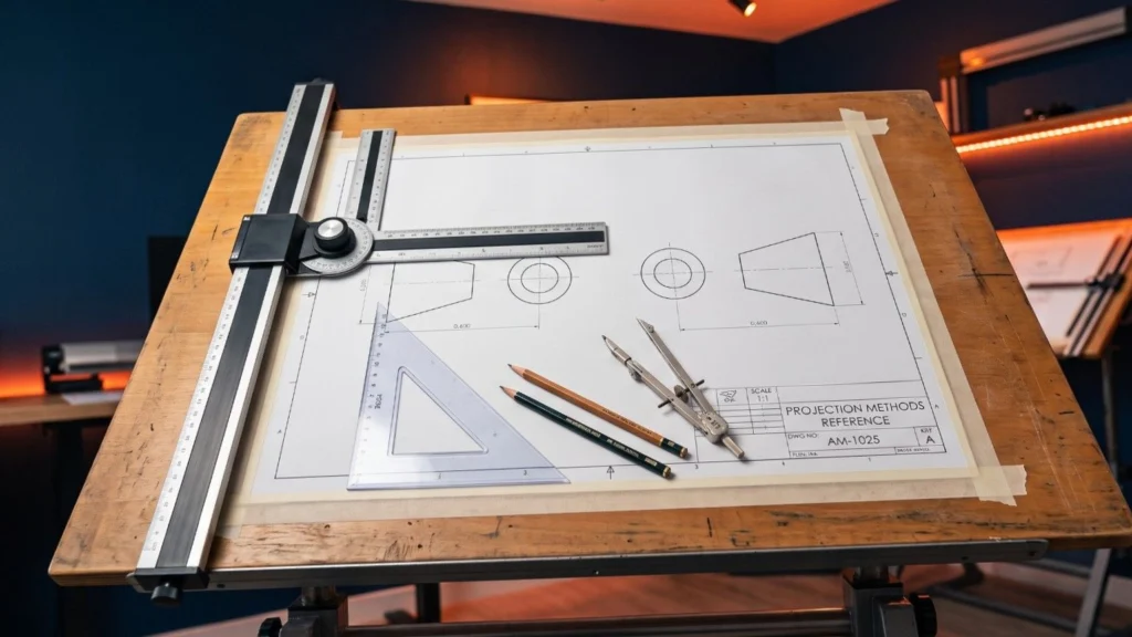
Understanding the first angle and third angle projection difference is a foundational requirement for interpreting orthographic blueprints across mechanical workshops and manufacturing industries. Mastering the first angle and third angle projection difference allows ITI fitter trainees, CITS instructors, and design engineers to correctly identify view placements, object quadrant positioning, and projection symbols. This comprehensive technical guide details the first angle and third angle projection difference under National Council for Vocational Training (NCVT) Craftsmen Training Scheme (CTS) standards, covering Bureau of Indian Standards (BIS IS: 15021) guidelines, reference planes, symbol geometry, and shop-floor blueprint reading rules.
📢 Share This Study Guide With Your Classmates & Friends!
📌 Guide Navigation Index
1. Principles of Orthographic Projection and Four Quadrant System
Orthographic projection is a technique used in engineering drawing to represent a three-dimensional object in two dimensions by projecting parallel sight rays perpendicular to a reference plane. When analyzing the first angle and third angle projection difference, understanding the spatial quadrant setup is essential.
Space is divided into four main quadrants by two intersecting principal planes: the Vertical Plane (VP) and the Horizontal Plane (HP). The line where these principal planes intersect is called the Reference Line or Ground Line (marked as X-Y).
1.1 The Four Quadrants and Planes of Projection
- First Quadrant: Situated Above the Horizontal Plane (HP) and In Front of the Vertical Plane (VP).
- Second Quadrant: Situated Above the Horizontal Plane (HP) and Behind the Vertical Plane (VP).
- Third Quadrant: Situated Below the Horizontal Plane (HP) and Behind the Vertical Plane (VP).
- Fourth Quadrant: Situated Below the Horizontal Plane (HP) and In Front of the Vertical Plane (VP).
1.1.1 Why Second and Fourth Quadrants Are Not Used
If an object is placed in the second or fourth quadrant, rotating the Horizontal Plane 90 degrees clockwise causes the Front View and Top View to overlap on the same side of the X-Y line, making the drawing unreadable.
2. First Angle Projection System Setup and View Layout Rules
In the First Angle Projection system, the 3D object is assumed to be placed in the First Quadrant. This system is widely used across India, European countries, and ISO-aligned manufacturing hubs.
2.1 First Angle Projection Principles for Technical Drawing
In First Angle Projection, the object lies between the Observer and the Projection Plane. The projection planes are assumed to be non-transparent (opaque).
2.1.1 View Alignment and Placement Rules
- Front View (Elevation): Projected on the Vertical Plane (VP) and drawn Above the X-Y reference line.
- Top View (Plan): Projected on the Horizontal Plane (HP) and drawn Below the X-Y reference line.
- Left-Hand Side View: Projected on the Profile Plane (PP) on the right side of the object, but drawn on the Right Side of the Front View.
- Right-Hand Side View: Projected on the Profile Plane (PP) on the left side of the object, but drawn on the Left Side of the Front View.
Before sketching orthographic projections, trainees configure their drafting equipment following guidelines from our manual on engineering drawing instruments and lines.
3. Third Angle Projection System Setup and View Layout Rules
In the Third Angle Projection system, the 3D object is placed in the Third Quadrant. This system is widely practiced in the United States, Canada, Japan, and ANSI-governed engineering industries.
3.1 Third Angle Projection Principles for Technical Drawing
In Third Angle Projection, the Projection Plane lies between the Observer and the Object. Therefore, the projection planes are assumed to be completely transparent.
3.1.1 Natural View Alignment
- Front View (Elevation): Projected on the Vertical Plane (VP) and drawn Below the X-Y reference line.
- Top View (Plan): Projected on the Horizontal Plane (HP) and drawn Above the X-Y reference line.
- Left-Hand Side View: Drawn on the Left Side of the Front View.
- Right-Hand Side View: Drawn on the Right Side of the Front View.
4. Comprehensive First Angle and Third Angle Projection Difference Matrix
Comparing the first angle and third angle projection difference helps clarify structural view arrangements for trade theory assessments:
5. Standard Projection Symbols and Truncated Cone Drafting Geometry
To prevent misinterpretation on shop floors, every technical drawing features an official projection symbol inside its Title Block (185 mm × 65 mm).
5.1 Drafting Geometry of Truncated Cone Symbols
The standard symbol is constructed using a truncated frustum of a cone placed horizontally.
- Major Diameter (D): Represents the base diameter of the frustum.
- Minor Diameter (d): Equal to 0.5 × D (half the base diameter).
- Frustum Length (L): Equal to the Major Diameter (D).
5.1.1 Symbol Symbolism Rules
In First Angle Projection, the two concentric circles (representing the frustum ends) are drawn on the right side of the trapezoid view. In Third Angle Projection, the concentric circles are drawn on the left side of the trapezoid view.
📄 Download Projection Methods PDF Reference Sheet
Get the complete official BIS IS: 15021 symbol geometry chart and quadrant rotation rules in a single PDF.
6. Horizontal Plane Rotation Mechanics (90-Degree Clockwise Rule)
After projecting 3D views onto reference planes, the 3D plane setup must be flattened into a 2D sheet format.
6.1 The 90-Degree Clockwise Rotation Rule
By international drawing conventions, the Vertical Plane (VP) remains stationary. The Horizontal Plane (HP) is rotated 90 degrees clockwise about the reference line (X-Y).
6.1.1 Resulting View Distribution
In First Angle Projection, rotating HP 90 degrees clockwise moves the Top View below the X-Y line. In Third Angle Projection, rotating HP 90 degrees clockwise moves the Top View above the X-Y line.
When dimensioning orthographic views on drawing sheets, students follow rules detailed in our guide on limit fit and tolerance hole basis system.
7. Global Industrial Usage (BIS, ISO, ANSI, and DIN Standards)
Understanding global adoption helps technicians read international engineering drawings correctly.
7.1 Standard Organizations Adoption Table
- Bureau of Indian Standards (BIS IS: 15021): Recommends First Angle Projection as the standard method for Indian industries and vocational training.
- International Organization for Standardization (ISO): Recognizes both systems, but specifies First Angle Projection as default across European industries.
- American National Standards Institute (ANSI): Specifies Third Angle Projection as standard across North American manufacturing.
- Japanese Industrial Standards (JIS): Primarily utilizes Third Angle Projection for automotive and electronics manufacturing.
8. NCVT, DGT & MSDE Exam Syllabus Alignment
Under Directorate General of Training (DGT) guidelines, mastering the first angle and third angle projection difference forms a critical component of Engineering Drawing assessments for ITI trainees.
8.1 NIMI Pattern Exam Weightage
Questions on orthographic projection principles, quadrant identification, and symbol drafting account for 15% to 20% of total marks in NCVT All India Trade Test (AITT) examinations. Official curriculum specifications can be reviewed via the Bharat Skills Official Portal and the MSDE Official Portal.
Before inspecting machined parts against projection blueprints, technicians verify dimensions using precision measurement tools and prepare threaded fasteners using fasteners types and applications manuals.
9. NIMI Pattern Mock Tests & Category Navigation
Master all technical questions regarding orthographic projections for upcoming NCVT AITT online Computer-Based Tests (CBT) across our study portals:
10. Frequently Asked Questions (NCVT CBT Exam Focus)
Q1: In which quadrant is the object placed during First Angle Projection?
Ans: The object is placed in the First Quadrant (Above the Horizontal Plane and In Front of the Vertical Plane).
Q2: Where is the Top View located relative to the Front View in First Angle Projection?
Ans: In First Angle Projection, the Top View is plotted below the Front View (Below the X-Y reference line).
Q3: Why are the projection planes assumed to be transparent in Third Angle Projection?
Ans: Because the projection plane lies between the observer and the object, requiring a transparent plane so the object can be viewed through it.
Q4: Which projection system is mandated by BIS IS: 15021 for Indian technical drawings?
Ans: Bureau of Indian Standards (BIS IS: 15021) mandates First Angle Projection as the primary system.
Q5: Where is the Left-Hand Side View drawn in Third Angle Projection?
Ans: In Third Angle Projection, the Left-Hand Side View is drawn on the Left Side of the Front View.
🚀 Ace Your NCVT AITT Online Examinations!
Practice official NIMI pattern mock tests across Trade Theory, Workshop Calculation & Science, and Employability Skills on Info ITI.