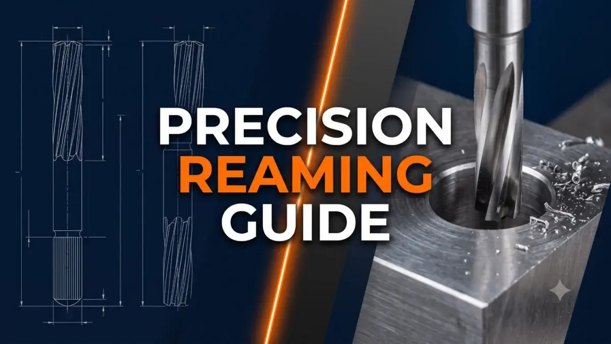
In high-precision manufacturing, producing a hole is only the preliminary step. The real challenge lies in perfecting its internal geometry, dimensional limits, and surface topography.
Achieving aerospace- or medical-grade tolerances requires a distinct, highly controlled secondary operation known as precision reaming. Whether you are an ITI machinist preparing for NCVT/CBT exams or an industrial CNC programmer, mastering this operation is vital for eliminating defects.
Therefore, keeping a handy precision reaming guide helps operators manage these tight constraints safely on the shop floor.
Table of Contents
1. What is Precision Reaming? Core Engineering Objectives
Precision reaming is a rotary cutting process designed to enlarge, trace, and refine pre-existing holes in a metal workpiece. When engineers look for a structural precision reaming guide manual, they focus on improving dimensional consistency across production lots. Unlike a drill bit that forces its path through solid stock, a reamer functions as a multi-edged finishing tool that shears away microscopic layers of metal.
This precision operation delivers sub-micron limits, consistently hitting tight tolerances down to ±0.0002 inches (±0.005 mm). Beyond sizing, it drops internal roughness to an impressive 10 to 25 microinches Ra, which often removes the need for internal grinding. Mechanically, it rectifies errors like hole ovality to ensure absolute roundness while shaving off subsurface tears and ragged burrs left behind by previous heavy drilling cycles.
2. Drilling vs. Reaming: The Operational Divide
Mixing up the structural boundaries between roughing and finishing operations ruins tools and leads to rejected parts. While a drill bit penetrates solid metal to establish the initial opening, a reamer follows behind solely to size and polish it. Utilizing a well-structured precision reaming guide checklist prevents operators from making critical loading errors during setup.
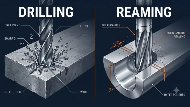
Drills clear out 100% of the cavity volume, but reamers remove a minimal allowance typically restricted to 0.004 to 0.015 inches (0.1 to 0.4 mm). This structural difference allows the reaming process in machining setups to deliver high-tolerance hole finishing down to ±0.0002 inches, whereas standard drilling yields basic industrial tolerances of ±0.005 inches.
To control heat, reaming operates at lower spindle speeds, usually 1/3 to 1/2 of the drilling baseline. Geometrically, instead of using two sharp cutting lips like a drill, a reamer distributes radial cutting pressure across 4 to 8 flutes. Experienced machinists know that a drill bit easily flexes or wanders when hitting hard spots, but a reamer naturally tracks the pre-existing centerline path without altering the original coordinates.
3. Industrial Reaming Allowance & Cutting Velocity Matrix
To prevent tool deflection and ensure absolute structural accuracy, you can refer to this compact reaming allowance chart before configuring your machine setup:
| Hole Diameter Bracket (mm) | Recommended Reaming Allowance (mm) | Cutting Speed Ratio (% of Drilling Baseline) | Target Finish Tolerance (inches) |
| Up to 6.0 mm | 0.15 mm | 10% to 30% | ±0.0002″ |
| 6.1 mm to 20.0 mm | 0.25 mm to 0.35 mm | 15% to 30% | ±0.0002″ |
| 20.1 mm and Above | 0.40 mm to 0.50 mm | 20% to 30% | ±0.0003″ |
Implementing the Technical Flow on the Shopfloor
Using the target values highlighted in the matrix ensures minimal tool wear. Following this data-driven precision reaming guide workflow keeps production lines predictable. Aligning your baseline parameters before launching automated cycles protects the machinery from unexpected vibration spikes.
4. Tool Metallurgy: What Are Reamers Made Of?
Industrial reamers must maintain ultra-sharp cutting edges under continuous friction, making material selection critical. As detailed later in this precision reaming guide, choosing the wrong substrate composition causes immediate edge degradation. High-Speed Steel (HSS) serves as the industry standard for manual hand reaming and general workshop production due to its excellent toughness.
For tougher applications involving stainless steels and titanium, premium-grade Cobalt Alloys (HSS-Co / M42) mixed with 5% to 8% Cobalt are utilized to handle higher thermal boundaries. High-speed automated CNC lines rely on Solid Tungsten Carbide for its extreme wear resistance over thousands of cycles. To enhance performance in dry, high-heat environments, modern CNC reamers are finished with micro-layers of low-friction Titanium Nitride (TiN) or Titanium Aluminum Nitride (TiAlN) coatings.
4.5 Tool Geometry: Decoding the Specific Angles
Understanding tool geometry is core to any engineering workflow. If you are looking for a complete precision reaming guide to eliminate sizing errors, analyzing the specific angles that dictate how the flutes shear metal is a mandatory step. Unlike drills, a reamer relies on subtle clearances to prevent rubbing and ensure a mirror finish.
4.5.1 Core Angles and Clearance Values
Every industrial tool relies on specific angular clearances to shear material accurately without inducing tool wear or structural micro-cracks. This comprehensive precision reaming guide overview highlights why these metrics prevent workpieces from falling victim to geometric distortion.
4.5.1.1 Entering Leading Edge Dynamics
4.5.1.1.1 Bevel Lead Angle Specification
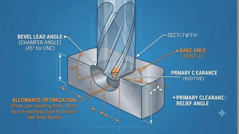
The bevel lead angle, or chamfer angle, is located at the front entering tip of the tool to facilitate initial hole entry. Any modern precision reaming guide states that this phase establishes the entry vector for the entire tool body. For standard hand operations, this metric is kept tight between 4 degrees and 6 degrees to allow for smooth manual alignment. On high-speed automated CNC machinery, the angle is increased to 45 degrees to maximize edge shearing efficiency.
4.5.1.1.2 Rake and Clearance Relief Limits
The rake angle controls chip curl velocity, typically set between 0 degrees and 5 degrees positive for structural steel, and up to 10 degrees positive for soft aluminum. Directly behind the cutting edge sits the primary clearance relief angle, calibrated strictly between 5 degrees and 7 degrees to eliminate tool body rubbing.
5. Historical Transformation: Traditional vs. Modern Reaming
The art of sizing holes has evolved significantly over the decades, completely shifting traditional shopfloor parameters. In the traditional era, reaming was highly dependent on a machinist’s tactile feel, dominated by hand reaming with basic carbon steel tools and uneven manual feeds. This historical transformation underscores why an updated precision reaming guide is essential for understanding automated toolpaths.
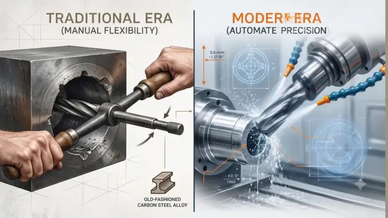
The modern era has replaced this with automated workflows, where high-pressure coolants flush out chips immediately to prevent scratches. Multi-axis CNC machines now align tools perfectly down to the micron, eliminating manual human error.
6. Strategic Industrial Sectors & Target Workspaces
Precision holes are structural prerequisites across modern industries where component failure is not an option. In the aerospace and aviation sectors, choosing the correct types of industrial reamers guarantees reliable interference-fit fastening holes in aircraft structures and jet engine turbine discs.
Automotive production lines apply automated reaming to size engine block cylinder liners, valve guides, and transmission gear cages. For medical engineering, polished solid carbide reamers finish bone implant tracts and surgical tools from titanium to prevent biological contamination. Adhering to a standardized precision reaming guide is a strict requirement for medical compliance audits. Additionally, the defense sector relies on this process for barrel chamber resizing and naval structural alignment templates.
7. The Machinist’s Blueprint: Step-by-Step Reaming Workflow
Turning a rough hole into a high-tolerance cylinder requires a systematic workshop sequence, starting with proper pre-drilling allowances. As per the standard parameters outlined in this precision reaming guide, you must never drill a hole to its final blueprint size beforehand. The premium metric rule is to keep the pre-drilled diameter roughly 0.2 to 0.4 mm smaller than the final target size, as shown in our data chart above.
1. Pre-Drilling Allowances
Ensure you calculate your machining allowances relative to the tensile strength of the target alloy. Applying the correct data from your precision reaming guide prevents tool chatter and keeps the workpiece from binding during operation.
2. Spindle Runout and Alignment Setup
Mount the tool securely because any minor runout causes the tool to cut oversized, leading to “bell-mouthing” at the hole entry. Always verify concentricity using a fine dial indicator before engaging the spindle.

3. Workpiece Rigid Clamping
Immobilize the workpiece on the machine bed using solid step blocks to eliminate micro-vibrations under torque. Weak setups compromise roundness and damage the internal wall profile.
4. Spindle Speed and Feed Rate Calibration
Configure the machine controls to low rotation speeds combined with smooth, steady feed movements. Keep the RPM low, about 10% to 30% of what you would use for a drill of the same size. Maintain a continuous feed profile between 0.1 and 0.5 mm per revolution (0.001 to 0.003 inches per rev).
ITI Core Formula: Calculating Reaming RPM
For ITI exams and workshop calculations, use the standard cutting speed formula:
Spindle Speed (RPM) = (1000 × V) / (π × D)
Where:
- RPM = Spindle Speed in Revolutions Per Minute
- V = Cutting Speed for reaming (in meters per minute, m/min)
- D = Diameter of the reamer (in mm)
- π = Constant value (Approx. 3.1416)
8. ITI Academic Framework & Competitive Exam Blueprint
For ITI Fitter, Machinist, and Turner trades under the NIMI pattern, reaming carries significant weight in NCVT and competitive government exams. Incorporating a trusted precision reaming guide into your study habits makes memorizing these complex tool angles much easier. Public sectors like ISRO (Technician-B), DRDO (CEPTAM), Railway Recruitment Board (RRB ALP), State Metro Corporations, and Ordnance Factories frequently target these concepts.
Real-World Competitive Exam Questions (NIMI Pattern)
Q1. Why are the cutting edges of a hand reamer unequally spaced?
- A) To reduce tool weight
- B) To simplify sharpening processes
- C) To reduce chattering and tool chatter vibration
- D) To increase cutting speed
- Correct Answer: C
Q2. What is the effect of a reamer having a tool runout error during machine setup?
- A) The hole will be undersized
- B) The tool will cut an oversized hole
- C) Perfect mirror surface finish
- D) Increased flute longevity
- Correct Answer: B
Q3. Which type of reamer is recommended for sizing a hole containing an internal keyway or slot?
- A) Straight flute hand reamer
- B) Helical/Spiral flute reamer
- C) Taper pin reamer
- D) Expansion reamer
- Correct Answer: B
Q4. What happens if the reaming allowance left before the operation is microscopic (too small)?
- A) Tool breaks instantly
- B) Surface finish becomes hyper-polished
- C) Reamer rubs instead of cutting, causing work-hardening and rapid edge wear
- D) Spindle stalls out
- Correct Answer: C
8.5 Metrology and Quality Inspection Standards
Achieving a high-tolerance internal cavity requires strict post-operation diagnostics to confirm that the surface topography aligns with international blueprints. Technicians must apply a structured inspection sequence immediately after the tool leaves the finished pocket. Reviewing your technical precision reaming guide documentation ensures that the correct grading instruments are chosen for the final inspection.
8.5.1 Advanced Metrology Tools for Precision Hole Sizing
Industrial quality control relies on precise mechanical instrumentation to audit completed components. Standard rulers or common calipers cannot measure sub-micron limits accurately, making advanced metrology tools essential for high-tolerance verification workflows.
8.5.1.1 Gauging Systems and Surface Roughness Metrology
To identify micro-defects like hourglassing, ovality, or positional deviations, machinists implement high-precision internal dial bore indicators calibrated to master setting rings. Utilizing a comprehensive precision reaming guide setup allows technicians to track exact dimensional values across multiple axial planes easily.
Following the dimensional inspection, an electronic stylus surface profilometer is used to map the internal cylinder wall texture. This evaluation ensures the internal finish remains within the premium 10 to 25 microinches Ra limit, verifying that the dynamic machining setup has achieved absolute geometric consistency.

Master Strategy: How to Crack Technical CBT Exams
Cracking the CBT requires mastering the standard NIMI question bank, as more than 80% of test questions draw directly from these resources. Reviewing specialized ITI fitter reamer questions regularly helps candidates remember standard allowance limits and memorize the pre-drilling material deduction rules across diameter brackets. Following a baseline precision reaming guide methodology keeps your exam prep efficient and focused.
Most importantly, avoid the rotation reversal trap. When asked how to remove a reamer from a hole, remember to always keep rotating in the forward direction while pulling the tool out, because reversing the spindle chips the cutting edges instantly.
9. Troubleshooting & Workshop Best Practices
Maintaining a zero-defect production line requires strict velocity control, keeping reaming speeds to roughly 1/2 to 2/3 of your drilling baseline to avoid intense localized friction. Following a structured precision reaming guide routine ensures you eliminate common defects before they cascade into scrap parts.
Machinists must strictly prohibit rotation reversal while the tool is inside the cavity, as back-turning destroys the polished finish. Regular maintenance includes constant flute inspection under magnification to catch built-up edge (BUE) micro-welding early. Lastly, perform rigorous runout audits with a dial test indicator before engaging the cut, ensuring runout never exceeds 0.0005 inches to prevent oversized holes.
10. Frequently Asked Questions (FAQ)
Q1: Why is my reamed hole coming out oversized or out-of-round?
Oversized or oval holes are typically caused by structural spindle runout, tool misalignment, or excessive cutting speeds that cause the tool to wobble off-center. Refer to our main precision reaming guide sections above to calibrate your alignment parameters.
Q2: Can I use a reamer to correct a hole that was drilled crooked?
No, because a reamer naturally follows the pre-existing centerline path. To correct positional or alignment errors, you must use a rigid single-point boring operation before final reaming.
Q3: How do I choose between a straight flute and a spiral flute reamer?
Straight flute reamers offer excellent stability in standard through-holes, while spiral flute reamers are necessary for blind holes or cylinders with internal slots to lift chips upward safely.
Q4: What happens if the reaming allowance is too small or too large?
An allowance that is too small causes the reamer to rub and create a work-hardened layer. An allowance that is too large overloads the cutting edges, leading to jammed chips and tool breakage.
11. Conclusion
Executing a flawless finishing process is what separates an amateur machinist from a premium precision engineer. Reaming tools remain irreplaceable components in high-tolerance sectors like aerospace and medical manufacturing because they bridge the gap between rough drilling and final, sub-micron geometric perfection.
By selecting the correct metallurgical grade, systematically regulating cutting speeds, controlling runout thresholds, and adhering to NIMI-validated shopfloor methodologies, you can eliminate component defects. Utilizing this practical precision reaming guide method transforms strict technical blueprint specs into highly repeatable manufacturing achievements.
🔍 Access Our Premium Study Resources
To get our verified technical guides and exam preparation tools, just follow these simple steps:
- Open a new tab and search for Info ITI on Google.
- Click on our official portal to access the complete workshop dashboard.
- Press Ctrl + D to Bookmark the site right now so you never lose track of premium machinist updates.
📱 Mobile User Tip: Tap the three dots in your mobile browser corner and select the Star icon to add us to your mobile bookmarks for instant shopfloor reference!