
Checking microscopic shaft runout or setting up a four-jaw lathe chuck requires extreme measurement precision on the shop floor. Mastering dial test indicator parts and uses helps machinists catch surface variations as small as a fraction of a millimeter. Unlike basic steel rules, this instrument magnifies small linear movements onto a clear circular dial face. Today, we break down dial test indicator parts and uses, how it works, how to read it, and key tips for NCVT CBT exams and practical job tests. For trade updates, explore the Info-ITI homepage.
1. What Exactly is a Dial Test Indicator?
A dial indicator is an indirect measuring tool used across engineering workshops. It does not measure the total length of a component from zero. Instead, it measures tiny height or alignment differences against a fixed reference block. An internal gear system converts small linear spindle motion into clear pointer rotation.
Learning dial test indicator parts and uses allows operators to test whether a shaft wobbles when spun on lathe centers. It also helps check if a vice jaw sits straight on a milling table. Getting comfortable with ITI fitter measuring instruments builds solid technical confidence during fitting work.
2. My First Experience with Dial Gauges During Apprenticeship
I am Parameswar Mohanta, and drawing from my 6+ years of practical industrial experience, I still fondly remember discovering dial test indicator parts and uses for the first time during my factory apprenticeship years ago. Mounting the magnetic stand onto the lathe bed and setting up a round bar in a four-jaw chuck felt tricky at first. Watching the pointer swing as I turned the chuck by hand taught me how sensitive and vital this precision tool really is on the shop floor.
Why Practical Shop Floor Training Teaches You What Books Cannot
Reading textbook diagrams gives you theory, but adjusting chuck jaws with a T-wrench while watching dial pointer movements teaches true muscle memory. Once you learn how to balance high and low spots practically, you never forget the skill.
Crucial Importance in NCVT CBT Exams & Public Sector Skill Tests
NCVT CBT theory papers frequently ask about dial test indicator least count values (0.01 mm), rack and pinion systems, and pre-load travel. In practical trade exams, examiners closely watch how you set up a dial gauge to align workpieces.
Railway ALP & DRDO Skill Test Scenarios
Recruitment exams for Railway RRB ALP, ISRO, DRDO, and Ordnance Factories test precision setups. During skill tests, candidates must mount an indicator on a magnetic base and record shaft runout accurately within a short time limit.
Mastering Dial Indicator Setup Under Timed Testing
Practicing indicator setups under timed conditions helps trainees avoid panic during official skill tests. Confidence comes from knowing how the dial indicator working principle functions under real shop conditions.
3. Complete Dial Test Indicator Parts and Uses Breakdown
To read readings accurately, you must know what each part does on the instrument. Technical standards maintained on the ISO International Standards Portal specify housing dimensions and mounting stem tolerances for dial test indicator parts and uses:
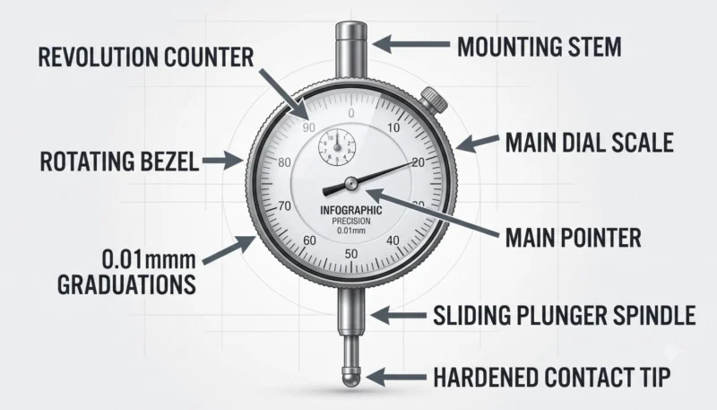
1. Rotating Bezel: An outer ring that turns the dial scale to zero out the pointer.
2. Main Dial Scale: Circular markings divided into 100 equal parts (each line equals 0.01 mm).
3. Main Pointer: Rotates across the scale to display surface variations.
4. Small Revolution Counter: Tracks full 1 mm turns made by the main pointer.
5. Sliding Plunger: A smooth steel spindle that moves when touching the job.
6. Contact Point: A small carbide sphere screwed onto the plunger end to prevent fast wear.
7. Mounting Stem: An 8 mm cylindrical shank clamped into magnetic stands.
8. Rack and Pinion Gears: Internal miniature gears that transfer straight spindle movement into pointer rotation.
Before inspecting shaft alignment with a dial gauge, review component mounting methods in our industrial machinery bearings guide.
4. Comparison: Plunger Type vs Lever Type Indicators
Executing a direct plunger vs lever type indicator comparison reveals key structural differences. Understanding these options helps technicians master dial test indicator parts and uses across different shopfloor setups:
| Feature | Plunger Type Indicator | Lever Type Indicator |
|---|---|---|
| Spindle Movement | Straight up-and-down linear movement | Pivoting arc movement on a lever arm |
| Travel Range | Longer travel (0 to 10 mm) | Shorter travel (0 to 0.8 mm) |
| Least Count | 0.01 mm (or 0.001 mm) | 0.01 mm |
| Best Used For | Flat surfaces, shaft runout, vice alignment | Reaching narrow keyways, slots, internal bores |
5. Common Beginner Mistakes & Practical Fixes
Avoid these four common mistakes to protect instrument accuracy and preserve dial test indicator parts and uses according to ASTM International Portal inspection guidelines:
1. Oiling the Plunger Spindle: Adding oil attracts grinding dust, turning into sticky sludge that jams internal gear teeth. Fix: Keep the sliding plunger completely clean and dry.
2. Measuring at Slanted Angles (Cosine Error): Placing the stylus at a steep angle causes inaccurate readings. Fix: Keep the contact tip perpendicular to the workpiece surface.
3. Forgetting Pre-Load Travel: Setting zero without pushing the plunger in slightly prevents reading low spots. Fix: Compress the plunger by about 0.5 mm before setting zero.
4. Loose Magnetic Stand Joints: Loose stand clamps wobble during testing. Fix: Tighten all stand locking knobs firmly before recording numbers.
Before marking out raw castings on a surface plate, review our marking punch tools breakdown.
6. Simple 5-Step Guide to Use a Dial Indicator
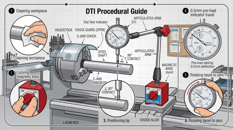
Even beginners can follow these five straightforward steps to apply dial test indicator parts and uses when checking shaft runout on a lathe:
1. Wipe Clean: Clean the workpiece surface and the indicator tip using a dry cloth.
2. Clamp Base: Lock the magnetic stand firmly onto a flat, stable machine bed.
3. Position Tip: Lower the contact tip until it touches the shaft straight on.
4. Apply Pre-Load: Push the indicator down slightly until the pointer moves 0.5 mm.
5. Zero Scale & Turn Shaft: Turn the outer bezel to line up 0 with the pointer, then rotate the shaft slowly by hand.
7. Download Dial Test Indicator Quick Revision PDF Sheet
Preparing for NCVT CBT trade theory exams or an upcoming Railway ALP skill test? Download our quick revision PDF sheet created by Parameswar Mohanta. This PDF summarizes least count rules, part names, pre-load setups, and shopfloor maintenance tips in a compact printable format for quick revision before your tests.
📥 Free Study Material: DTI Quick Revision Sheet (PDF)
Official Info-ITI Trade Theory Notes for ITI Fitter, Turner & Machinist Students
📄 Download PDF Revision Sheet Now8. NCVT CBT Mock Test (NIMI Pattern) – Dial Test Indicator
Practice essential trade theory questions designed strictly on the official NIMI pattern. This 10-question online mock test covers core NCVT CBT exam topics including least count calculation, rack and pinion mechanisms, pre-load settings, and cosine error rules. Test your knowledge on Google Forms and receive your score instantly.
📝 NCVT CBT Mock Test (NIMI Pattern 10 MCQs)
Official NIMI Question Bank Pattern for ITI Fitter, Turner & Machinist Trainees
🎯 Attend NIMI Pattern Mock Test NowFor preliminary angular layout verification before setting up magnetic bases, read our combination set parts and uses guide.
🚀 Master Workshop Calculation & Theory Notes
Explore trade theory lessons, mechanical calculation guides, and public job alerts with our expert resources:
9. Pros and Cons of Dial Test Indicator Parts and Uses
Understanding tool limitations helps you evaluate dial test indicator parts and uses for specific fitting tasks:
1. Advantages: Measures small variations down to 0.01 mm, offers clear pointer movement, fits easily on magnetic bases, and speeds up chuck alignment.
2. Disadvantages: Sensitive to shocks or drops, requires a rigid mounting stand, cannot measure overall length directly, and internal gears stick if exposed to dirty oil.
10. Workshop Helpdesk & Trainee Q&A
Have a doubt about pre-load travel or understanding dial test indicator parts and uses for your NCVT CBT exam? Leave your question in the comments below! Our team answers daily to clear your doubts.
11. Frequently Asked Questions
What is the least count of a standard metric dial indicator?
The least count of a standard metric dial test indicator is 0.01 mm. Micron indicators offer 0.001 mm resolution.
What are the main parts of a dial test indicator?
Key parts include the rotating bezel, main dial scale, pointer, revolution counter, sliding plunger, contact point, stem, and internal rack and pinion gears.
Why should you keep the plunger spindle dry?
Oil on the plunger collects dust and metal filings, creating sludge that clogs delicate internal gear teeth.
What is pre-load travel on a dial gauge?
Pre-load is compressing the plunger by about 0.5 mm before setting zero, enabling the pointer to read both high and low surface spots.
How is a dial indicator useful in lathe work?
It helps align cylindrical stock in four-jaw chucks and checks shaft wobble before turning.
What causes cosine error?
Cosine error happens when the contact stylus touches the job at a steep angle instead of perpendicular to the surface.
12. Final Thoughts on Dial Test Indicator Parts and Uses
Understanding dial test indicator parts and uses builds valuable practical skills for workshop fitting and machine alignment tasks. Knowing plunger and lever indicator differences, 0.01 mm least count rules, and pre-load steps prevents inspection mistakes. Proper care ensures long-term tool accuracy.
For more technical trade theory guides and exam preparation updates, visit the Info-ITI Homepage!