In precision engineering, dimensional accuracy dictates the performance of any machined component. A single layout error can compromise structural tolerances, leading to material waste and mechanical failure. To ensure optimum workshop efficiency, mechanical technicians rely on multi-functional layout tools. Among these, the combination set stands out as one of the most versatile and precise instruments utilized in modern industrial machine shops. For global technicians, workshop engineers, and vocational students worldwide, mastering the application of Combination Set Parts and Uses is not just an academic milestone; it is a critical career skill that directly impacts product quality and industrial efficiency.
Whether you are performing structural markup, validating a ninety-degree machining configuration, or determining the center axis of a cylindrical shaft, understanding the underlying framework of this tool is essential. For ITI students preparing for their upcoming NCVT Computer-Based Test (CBT) or mechanical technicians looking to advance their shop-floor expertise, this complete guide covers everything from basic operational mechanics to high-yielding exam score strategies.
Table of Contents
🛠️ Detailed Breakdown of Combination Set Parts and Uses
To truly understand how this multi-tool improves workshop efficiency, we must analyze the structural framework of the Combination Set Parts and Uses. This instrument is not just a single tool but a modular ecosystem designed for dynamic layout challenges. The core function relies on an interchangeable system where three distinct measurement heads slide onto a single heavy steel rule blade. By using these elements together, a technician can switch from linear measuring to angular markup in seconds.

The entire operating system depends on a deep, precision-milled tracking channel. When you adjust any component, the built-in clamp hook seating ensures that you maintain absolute alignment. Understanding the interaction between the blade guide and the individual locking assemblies is the first step toward master-level precision on the shop floor.
🛠️ What is a Combination Set? (Definition & Working Principle)
A combination set is a heavy-duty, multi-purpose measuring and layout instrument (मापने aur मार्किंग करने wala औजार) that combines the functional capabilities of a steel rule, square head, protractor, and center locator into a single coordinated system. Unlike single-purpose layout instruments, this versatile layout framework permits multiple geometric evaluations without requiring the technician to switch tools continually. This integrated approach minimizes measurement transfer errors and accelerates manufacturing layouts.
The Working Principle: The entire architecture relies on an interchangeable component sliding system (बदले जाने वाले पुर्जों ka स्लाइडिंग सिस्टम). The individual measuring heads feature a small alignment hook bolt that seats perfectly inside a deep, precision-milled longitudinal channel (नाली) running along the entire length of the steel rule blade. This design allows the heads to slide freely along the blade and lock securely at any position using a standardized knurled nut assembly, keeping all measurement faces perfectly square or aligned relative to the reference edge.
📐 Comprehensive Technical Diagram Layout
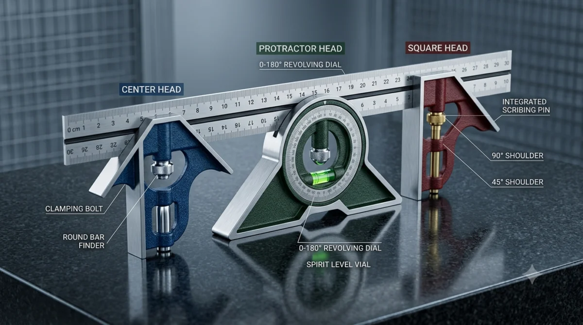
To deploy this instrument effectively on the shop floor, technicians must visualize how each distinct component interfaces with the heavy steel blade. The diagram below illustrates the modular layout and adjustment points of a standard industrial combination set configuration:
1. CENTER HEAD
• Bisects round iron stock
• Finds cylinder center axis
2. PROTRACTOR HEAD
• 1-Degree Least Count limit
• Includes Spirit Level glass
3. SQUARE HEAD
• Houser for Scribing pin
• Level verification checking
As highlighted in the visual alignment layout, this tool functions via coordinated sub-units. Now, let us advance into a comprehensive step-by-step breakdown of each component to understand their individual engineering operations on the floor.
📐 Dynamic Architectural Diagram of Combination Set Parts and Uses
To truly visualize how a multi-functional layout tool functions on a busy machine shop floor, we must look closely at its physical orientation. An accurate blueprint layout provides technicians and students with a clear mental map of how the different modular components lock together.
The interactive layout illustration below provides a detailed structural view of the Combination Set Parts and Uses framework. It highlights how the three interchangeable measuring assemblies connect seamlessly onto a single rigid tracking rail:
✓ 90° V-Anvil Alignment
→ Finds Round Bar Axis
✓ 0° to 180° Rotating Disk
💡 Integrated Spirit Level
✓ Fixed 90° & 45° Shoulders
💡 Level Alignment Verification
🏗️ Technical Construction and Types of Material Used
In industrial manufacturing, structural stability is mandatory for layout tools. A tool that warps or rusts due to temperature changes or coolant exposure becomes useless.
- The Blade Construction: Standard high-grade combination sets feature a rule blade made from Hardened and Tempered Stainless Steel (कठोरीकृत aur टेम्पर्ड स्टेनलेस स्टील) or heavy alloy tool steel. This special heat-treatment process ensures the blade resists bending stresses and structural wear. The scales are deep photo-etched into the metal surface so they remain perfectly readable even when covered in grease or machine oil.
- The Component Heads: The bodies of the square, center, and protractor heads are typically manufactured from Close-Grained Cast Iron (घना ढवां लोहा) or drop-forged high-carbon steel. The checking faces are precision-ground flat to remove surface irregularities, ensuring maximum contact accuracy against the stock material. A durable textured enamel paint coating is applied to the non-machined portions to guard against atmospheric corrosion.
🔍 Four Core Component Parts and Their Specialized Workshop Uses
The modular operational capacity of this tool depends entirely on its four primary elements. Each sub-assembly features specialized functional surfaces that conform to structural and mechanical principles.
1. The Heavy Steel Rule (The Foundation Blade)
The foundation of the entire system is the precision-ground steel rule blade. A deep, precision-milled structural groove (नाली) runs along the entire length of one side of the blade, serving as a straight guide rail for the clamping bolts of the three attachable heads.
The face of the blade is marked with clear, wear-resistant graduations. High-grade engineering sets feature photo-etched markings that include both metric divisions (millimeters and half-millimeters) and imperial scales (inches and fractional divisions). The edges are precision-ground flat to provide an absolute straight-edge reference line for scribing layout lines.
2. The Square Head (90° and 45° Layout Engineering)
The square head is the most frequently deployed component in workshop operations. It features two precision-ground reference shoulders:
- The Perpendicular Face: Positioned at an absolute angle of exactly 90° relative to the rule blade, utilized to check structural squareness and scribe vertical layout lines.
- The Miter Face: Configured at an angle of exactly 45°, enabling rapid checking and marking of standard structural chamfers and miter joints.
Additionally, a high-precision glass spirit level tube (स्प्रिट लेवल) is integrated directly into the body of the square head to verify horizontal alignment. A hardened steel scribing needle (स्क्राइबर सुई) is also housed within a dedicated internal storage slot, secured by a small knurled thumb screw for rapid layout marking on the metal stock.
3. The Protractor Head (Angular Measurement Layout)
When layout work requires non-standard angular configurations, the protractor head is mounted to the blade. This component consists of a heavy base frame housing a central revolving turret disk. The circular turret features scale markings running from 0° to 180° in both directions.

The protractor head includes its own independent spirit level assembly, mounted onto the revolving turret. By loosening the twin turret locking screws, a technician can rotate the scale disk to align the bubble to center, allowing the measurement of inclined plane angles relative to the horizontal earth plane.
4. The Center Head (Locating Cylindrical Centers)
The center head features a specialized V-shaped structural anvil body. The internal clamping surfaces form a precise 90° opening angle. When the head is locked onto the steel blade, the top measuring edge of the rule bisects this 90° angle perfectly.

This geometric symmetry allows technicians to slide the internal surfaces of the V-anvil against the exterior wall of any round steel bar, pipe, or shaft stock. Scribing a line along the edge of the rule, rotating the shaft roughly 90° , and scribing a second line provides an absolute intersection mark that pinpoints the exact physical center axis (केंद्र बिंदु) of the cylindrical workpiece.
📊 Technical Specifications: Accuracy and Least Count Matrix
To maintain the quality demands of modern mechanical manufacturing, every instrument must operate within strict international tolerance levels. The operational reliability of the combination set is determined by the distinct resolution and precision limits of its individual measuring elements.
The following data matrix outlines the technical specifications, standard calibration values, and structural functions of the individual components:
| Component | Measuring Capabilities | Accuracy / Least Count Limits | Core Industrial Application |
| Precision Steel Rule | Linear Dimensions & Depth Profiles | 0.5 mm & 1/64th inch fractional markings | Direct linear measurement and straight-edge verification |
| Square Head Shoulders | 90° Perpendicularity & 45° Miters | ± 5 minutes of arc angular tolerance | Squaring material stocks and marking angular chamfers |
| Protractor Head Dial | 0° to 180° Angular Orientations | 1 Degree resolution minimum limit | Custom angular layout and bevel inspections |
| Center Head V-Anvil | Cylindrical Diameter Tracking | Central alignment within 0.05 mm | Locating structural center points on round stock |
| Integrated Spirit Level | Plane Horizon Positioning | 30 minutes of arc per bubble displacement | Leveling industrial machinery beds and fixtures |
⚖️ Technical Performance Profile: Advantages and Disadvantages
Advantages (फायदे)
- Space & Cost Optimization: Instead of buying four separate precision layout tools, a student or small machine shop gets everything inside one compact wooden storage box.
- Time-Saving Flexibility: A lathe machine turner or bench fitter can switch from scribing a parallel layout line to checking a 45-degree chamfer edge in less than ten seconds, accelerating overall production cycles.
- Dual-Axis Level Verification: The built-in spirit level glass allows simultaneous verification of vertical squareness and horizontal alignment of a structure.
Disadvantages (नुकसान)
- Vulnerability to Contamination: The longitudinal guide rail groove on the steel rule acts as a trap for metallic filings and abrasive grinding dust. If not cleaned constantly, it can cause the clamping mechanism to jam or introduce alignment errors.
- Tolerance Stack-Up Over Time: Because it contains moving joints and removable components, heavy wear on the clamping hook bolt can introduce minute measurement errors over years of continuous service. For laboratory calibration certification, a solid, non-adjustable master block square remains preferred.
🎓 Vocational Blueprint: Strategic Importance for ITI Students & Competitive Exams
For vocational students under NCVT (National Council for Vocational Training) frameworks, the study of Combination Set Parts and Uses carries immense weight. The Computer-Based Test (CBT) and practical engineering drawing exams consistently feature technical questions regarding this instrument. In typical competitive technical exams, this section contributes around 6 to 10 marks, which can easily determine a student’s final ranking.
Expected CBT Question Patterns & Exam Focus Areas
- Visual-Based Identification: Computer screens during CBT exams frequently display a line drawing of a single head assembly and ask the student to select the correct component name from a multiple-choice menu.
- Least Count Computations: Questions frequently test your memory on the exact numeric limitations of the dial scale, expecting the standard answer of 1°.
- Material Reason Justifications: Examiners look for structural understanding, such as why high-grade stainless steel is chosen for the rule blade body to minimize errors caused by thermal expansion or surface rust.
🏭 Practical Examples and Real Industrial Applications
To understand how this layout instrument functions outside the classroom, consider these real-world manufacturing applications:
- Case Example A: General Shop Bench Fitters: Before starting a manual hack-saw cut on a thick carbon steel flat bar, a bench fitter uses the square head to mark an absolute 90-degree guide line from the stock’s machined reference boundary.
- Case Example B: Heavy Fabrication Welders: Before structural arc-welding two heavy hollow pipes into a frame, the welder slides the protractor head along the rule, sets the rotary dial to exactly 60°, and scribes the angular bevel cut line to match the project blueprint.
- Case Example C: CNC Lathe Machine Turners: When a round metal bar needs to be mounted perfectly square inside a four-jaw machine chuck, the machinist uses the center head to cross-scribe two intersecting lines across the raw end face, revealing the true central axis point within seconds.
🚶 Step-by-Step Guide: How to Use a Combination Set Safely
Using a precision mechanical tool correctly requires a disciplined operational sequence to prevent errors and avoid damaging the instrument’s calibrated reference faces.
1. Clean and Prepare the Reference Components:
Step 1. Before assembling any components, wipe down the steel rule blade, the internal channels of the measuring heads, and the workpiece surface using a clean, lint-free cloth. Metal chips, grease, or grit trapped inside the blade groove will cause the clamping bolt to jam or throw the head out of alignment, introducing measurement errors.
2. Mount and Align the Target Head:
Step 2. Loosen the knurled locking nut on the selected head until the internal hook bolt drops slightly into the slot window. Align the hook with the rule’s longitudinal channel and slide the head onto the blade from either end. Move the head to the desired dimensional marking on the scale.
3. Lock the Position Securely:
Step 3. Tighten the knurled thumb nut with firm finger pressure.
⚠️ Critical Handling Warning: Never use pliers or mechanical wrenches to tighten the locking bolts. Applying excessive torque can deform the soft hook bolt assembly or score the precision-ground channel edges of the steel blade, permanently ruining the instrument’s accuracy.
4. Perform the Geometric Layout or Measurement:
Step 4. Press the ground reference face of the head firmly against the machined edge of the workpiece. Ensure no gaps exist between the material and the tool surface. Use the scribing needle to mark clean layout points, keeping the needle angled slightly outward against the blade edge for maximum precision.
🛡️ Industrial Maintenance Protocols for Precision Tools
Mechanical layout instruments are continuously exposed to cutting fluids, heat variations, and abrasive particulate matter on the shop floor. Implementing strict maintenance protocols preserves the geometric accuracy of the tool over a long operational lifespan.
- Corrosion Management: Sweat from a technician’s hands contains acids that accelerate surface oxidation on high-carbon steel parts. After every shift, wipe down all exposed steel components with a clean cloth damp with light anti-rust industrial oil or specialized machine lubricant.
- Storage Environment: Never store a combination set inside a drawer, loose alongside heavy cutting bits, hand files, or machine wrenches. Mechanical impacts can dent or nick the ground edges of the rule and faces, destroying the alignment of the system. Always return the components to their fitted protective storage case.
- Burr Removal Verification: Periodically inspect the reference edges of the square and center heads using a magnifying lens. If a burr develops from contact with rough castings, remove it gently using an ultra-fine oil stone, taking care not to alter the primary ground angles.
📝 Academic Quick Revision Notes (Short Notes for Fast Learning)
- 📝 Core Material Framework: Rule blade is stainless steel (hardened/tempered); functional heads are heavy, close-grained cast iron.
- → Protractor Least Count: Dial resolution is exactly 1°.
- ✓ Angular Face Limits: Square head provides automatic profiles for exactly 90° and 45°.
- 💡 The Guide Rail Purpose: The longitudinal center slot houses the clamp hook bolt to maintain linear alignment without sideways play.
- 📝 Essential Accessories: The square head body contains a built-in removable steel scriber needle and horizontal glass spirit level tube.
- ✓ Primary Center Principle: The center head V-groove forms a precise 90° angle, allowing the blade edge to bisect the geometric midpoint of any round cylinder.
✏️ Practice Section: High-Yield Multiple Choice Questions (MCQs)
Q1. What is the standard accuracy or minimum reading capability (least count) of a combination set protractor head dial scale?
A) 1 Minute
B) 5 Minutes
C) 1° (1 Degree)
D) 0.5°
Answer: C
Q2. Which measuring component assembly should be chosen to locate the central alignment coordinates of a solid steel pipe shaft?
A) Square Head
B) Protractor Head
C) Center Head
D) Spirit Level Glass
Answer: C
Q3. The deep central groove extending along the full length of the combination set steel rule blade performs what technical function?
A) It reduces the structural weight of the tool
B) It acts as a fluid drain for cooling lubricants
C) It receives the internal hook bolt to guide and slide the attachments smoothly
D) It allows the technician to measure external thread pitches
Answer: C
Q4. What pre-set geometric angles are built directly into the ground shoulders of a standard workshop square head?
A) 90° and 60°
B) 45° and 45°
C) 90° and 45°
D) 180° and 90°
Answer: C
💬 Professional Viva & Job Interview Questions
Q1. Why are you strictly prohibited from using hand tools like pliers to tighten the clamping nut of a combination set head?
Ans: The internal tracking assembly relies on a small hook bolt that interfaces with the rule’s center groove. If mechanical force is applied via pliers, the excess torque can bend or snap the clamping hook or warp the ground tracking channel of the blade, permanently ruining the instrument’s accuracy.
Q2. What is the practical operational benefit of having a spirit level glass integrated inside both the square head and protractor head housings?
Ans: The spirit level allows the technician to ensure the workpiece or machine bed remains level relative to the earth’s horizontal plane while simultaneously performing vertical squareness or angular bevel markups. This prevents cumulative errors across multi-axis industrial setups.
🏁 Architectural Conclusion: Elevating Workspace Standards
In summary, mastering the setup of Combination Set Parts and Uses is an absolute necessity for modern manufacturing environments. From the precision demands of international manufacturing lines to the high-stakes environment of NCVT computer-based testing, this tool serves as a bridge between structural designs and real-world physical components. By mastering its parts, respecting its calibration limits, and maintaining its clean surfaces, you protect your workmanship from errors and build a reputation for true engineering excellence.
🚀 Join the Premium Info-ITI Learning Community!
If you want to stay ahead of the curve with deep-dive technical insights, professional trade secrets, and proven exam-cracking strategies, make sure to bookmark Info-ITI in your browser! Whenever you face a complex tool calibration issue or need an authoritative layout guide on the shop floor, simply type Info-ITI into Google to access our growing library of premium engineering assets.
Don’t keep this valuable resource to yourself; share this comprehensive structural guide with your fellow workshop technicians and ITI classmates across your WhatsApp student groups. Drop your thoughts in the comment section below and tell us which core mechanical tool you want us to break down next!

Parameswar Mohanta
I am a NCVT-certified ITI expert (86% score) and a Full-stack Web Developer. As the founder of Info-ITI, I leverage my 6+ years of experience to provide high-quality NIMI-pattern mock tests and career guidance to ITI students nationwide.
