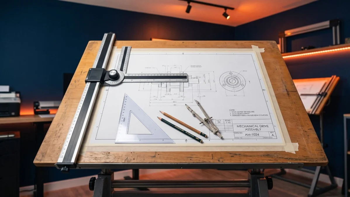
Engineering drawing instruments and lines form the universal graphical language used by engineers, designers, and industrial technicians to convey manufacturing instructions clearly. Mastering essential engineering drawing instruments and lines enables ITI fitter trainees, CITS instructors, and design draftsmen to create precise technical blueprints without visual ambiguity. This comprehensive technical guide covers engineering drawing instruments and lines under National Council for Vocational Training (NCVT) Craftsmen Training Scheme (CTS) standards, detailing Bureau of Indian Standards (BIS) specifications, drawing board sizes, sheet layout dimensions, line thickness groups, lead pencil hardness selections, and shop-floor blueprint inspection rules.
📢 Share This Study Guide With Your Classmates & Friends!
📌 Guide Navigation Index
1. Master Selection Guide for Engineering Drawing Instruments and Lines
Engineering drawing is a graphical language used by engineers, technicians, and skilled craftsmen to convey ideas, structural dimensions, and manufacturing instructions. Working effectively with engineering drawing instruments and lines requires utilizing high-precision tools designed to eliminate visual ambiguity.
In technical workshops, executing engineering drawing instruments and lines routines requires strict adherence to standardization guidelines issued by the Bureau of Indian Standards (BIS) and the International Organization for Standardization (ISO).
1.1 Primary Mechanical Drafting Tool Kit
- Drawing Board: Provides a flat, smooth wooden surface for mounting paper sheets.
- T-Square: Draws horizontal parallel lines and acts as a sliding guide for set squares.
- Set Squares: Triangular tools for constructing vertical and angled lines.
- Mini Drafter: Combines the functions of a T-square, set square, protractor, and scale into a single adjustable mechanism.
- Instrument Box: Contains precision compasses, dividers, and extensions for drawing circles and arcs.
1.1.1 Tool Maintenance and Care Protocols
Clean instrument edges before drawing. Never use plastic set squares as cutting guides with utility knives. Store compass points in protective covers to prevent tip dulling.
2. Drawing Board Classifications and T-Square Specifications (BIS IS: 1444)
The foundation of manual technical drafting rests on the quality of the drawing board. Selecting appropriate equipment aligned with engineering drawing instruments and lines standards ensures drawing accuracy.
2.1 Drawing Board Sizes D0 to D3 BIS Standard Specifications
Drawing boards are manufactured from well-seasoned soft wood strips such as pine or fir. They feature a straight ebony edge strip inserted along the left side to guide the T-square stock smoothly.
The standard drawing board sizes D0 to D3 BIS standard specifications are outlined below:
2.2 T-Square Construction and Alignment
A T-square consists of a wooden or plastic stock and a long blade joined at a rigid 90-degree angle. The stock slides along the ebony working edge of the board to draw parallel horizontal lines.
2.2.1 Operating Rules for T-Squares
Always press the inner working face of the stock firmly against the left edge of the board. Draw lines from left to right along the top working edge of the blade only.
Prior to measuring physical components for layout drawings, trainees utilize accurate precision measurement tools to verify part dimensions.
3. Set Squares, Protractors, and Mini Drafter Applications
Combining set squares with a T-square expands line construction capabilities. Understanding how these tools work together improves drafting speed and precision.
3.1 Application Rules for Engineering Drawing Instruments and Lines
Set squares are transparent plastic triangles used to construct vertical and inclined lines.
- 30°- 60° Set Square: Contains 30-degree, 60-degree, and 90-degree internal angles. The long hypotenuse measures approximately 250 mm.
- 45° Set Square: Contains two 45-degree angles and one 90-degree angle. Used for drawing 45-degree section hatching lines.
3.1.1 Angular Combinations
By placing set squares together over a T-square blade, draftsmen can construct angles in increments of 15 degrees (such as 15°, 75°, 105°, and 135°).
3.2 Mini Drafter Setup and Advantage
A mini drafter clamps to the top-left corner of the drawing board. It features two adjustable scale blades fixed at 90 degrees, connected to a swiveling protractor head and parallel linkage bars.
Using a mini drafter speeds up work by replacing the separate T-square, set squares, and protractor.
4. Precision Compasses, Dividers, and French Curve Selection
Drawing circles, arcs, and irregular curves requires specialized tools from a drawing instrument box.
4.1 Compass Selection and Adjustment
Large compasses draw circles up to 150 mm in diameter. Small bow compasses feature a central adjusting thumb-screw to draw small precision circles under 25 mm in diameter without leg slipping.
4.1.1 Lengthening Bar Extension
Inserting a lengthening bar into a large compass leg extends its radius to draw large circles up to 300 mm in radius.
4.2 Dividers and French Curves
- Dividers: Used for transferring dimensions from scales to paper and stepping off equal distances.
- French Curves: Clear acrylic templates used to draw smooth non-circular curves through plotted coordinates.
Before sketching threaded machine fasteners, students review definitions in our guide on fasteners types and applications.
📄 Download Engineering Drawing Formula PDF Blueprint
Get the complete official BIS line thickness reference sheet and drawing board setup manual in a single high-resolution PDF.
5. Standard Drawing Sheet Layout Sizes A0 to A4 (BIS IS: 10711)
Technical drawing sheets follow strict international aspect ratios (1:√2). The Bureau of Indian Standards (BIS IS: 10711) specifies standard paper sizes.
5.1 International ISO Paper Series Specifications
The standard drawing sheet layout sizes A0 to A4 maintain constant proportional dimensions across trimmed and untrimmed formats:
5.2 Title Block Dimensions and Positioning
The title block is placed at the bottom-right corner of every drawing sheet. Standard dimensions are strictly 185 mm in length and 65 mm in height.
It contains critical information: Title of Drawing, Name of Institute, Scale, Symbol of Projection (First Angle or Third Angle), Drawing Number, and Approval Signatures.
6. Types of Lines in Engineering Drawing BIS IS 10714 Conventions
Lines are the primary elements of technical drawings. Line thickness, style, and contrast convey specific structural information.
6.1 Standard Line Classifications
Under BIS IS 10714 standards, types of lines in engineering drawing bis is 10714 are categorized into distinct functional groups:
6.1.1 Line Precedence Rules
When two or more lines coincide at the same location, plot them in this priority order: 1. Visible Outlines (Type A), 2. Hidden Outlines (Type E/F), 3. Cutting Planes (Type H), 4. Center Lines (Type G).
To verify dimensional tolerances on sectional views, draftsmen apply the limit fit and tolerance hole basis system.
7. Lead Pencil Hardness Grades for Technical Drawing and Lettering Rules
Pencil lead grade selection directly affects line thickness and contrast.
7.1 Lead Pencil Hardness Grades for Technical Drawing Mappings
Understanding lead pencil hardness grades for technical drawing ensures clean, smudge-free drawings:
- Hard Grades (4H to 9H): 4H and 3H pencils are used for light construction lines and initial layouts.
- Medium Grades (H, 2H, 3H): 2H pencils are used for center lines, dimension lines, and hidden lines. H pencils are used for visible outlines.
- Soft Grades (HB, B, 2B): HB pencils are used for freehand sketching and single-stroke lettering.
7.2 Standard Technical Lettering (BIS IS: 9609)
All text on technical drawings must use single-stroke gothic lettering for legibility. Lettering can be vertical or inclined 75 degrees to the right.
Standard heights for lettering are: 2.5 mm, 3.5 mm, 5 mm, 7 mm, 10 mm, 14 mm, and 20 mm.
8. BIS Dimensioning Systems and Arrowhead Conventions
Dimensioning provides numerical sizes and manufacturing instructions. All dimensions are expressed in millimeters unless noted otherwise.
8.1 Aligned vs Unidirectional Systems
- Aligned System: Dimensions are placed perpendicular to the dimension line so they can be read from the bottom or right side of the sheet.
- Unidirectional System: Dimensions are placed horizontally in breaks along the dimension line, read from the bottom of the sheet only.
8.1.1 Arrowhead Proportion Rules
Arrowheads must be filled solid. They require a length-to-width ratio of 3:1.
Before dimensioning sheet metal layouts, students consult tools covered in our sheet metal tools and joints practical manual.
9. NIMI Pattern Mock Tests & Category Navigation
Master technical questions regarding engineering drawing instruments and lines for upcoming NCVT All India Trade Test (AITT) online Computer-Based Tests (CBT) across our study portals:
10. Frequently Asked Questions (NCVT CBT Exam Focus)
Q1: What is the trimmed dimension of an A2 drawing sheet under BIS IS: 10711?
Ans: The trimmed dimension of an A2-size drawing sheet is 420 mm × 594 mm.
Q2: Which line type is used to represent hidden outlines and hidden edges in engineering drawings?
Ans: Type E / F Dashed Thin lines (0.25 mm thickness) are used to represent hidden outlines and hidden edges.
Q3: What is the standard length-to-width ratio of an arrowhead in engineering dimensioning?
Ans: The standard length-to-width ratio of a solid filled arrowhead is 3:1.
Q4: Which drawing board designation corresponds to an A1 size drawing sheet?
Ans: Drawing board D1 (1000 mm × 700 mm × 25 mm) corresponds to an A1 size drawing sheet.
Q5: What pencil grade is recommended for drawing centerlines and dimension lines?
Ans: A 2H hard pencil is recommended for drawing thin centerlines, extension lines, and dimension lines.
🚀 Ace Your NCVT AITT Online Examinations!
Practice official NIMI pattern mock tests across Trade Theory, Workshop Calculation & Science, and Employability Skills on Info ITI.