
Dimensional accuracy is the core backbone of precision mechanical fitting and workshop production. Whether you are an ITI student preparing for your upcoming NCVT AITT examination or a technician working in industrial quality control, mastering shop-floor measuring devices is essential. This technical handbook serves as your complete vernier caliper and micrometer least count guide, covering mathematical formulas, zero error adjustments, and NCVT Craftsmen Training Scheme (CTS) standards.
📌 Guide Navigation Index
1. Least Count Fundamentals & Mathematical Formulas
In workshop metrology, the least count of a measuring instrument defines the smallest dimension that can be accurately measured by that tool. Standard workshop steel rules offer basic precision down to 0.5 mm. However, high-grade engineering assembly, jig manufacturing, and engine reboring require tolerances measured in hundredths of a millimeter.
This practical vernier caliper and micrometer least count guide allows trainees to understand exact mathematical derivations, preventing costly scrap rates during practical trade training.
1.1 Vernier Caliper Least Count Derivation
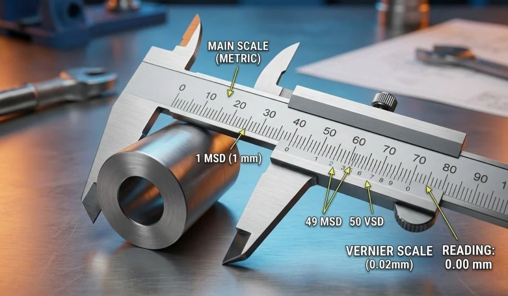
The operational principle of a Vernier scale relies on using two slightly different scale divisions. The vernier caliper least count formula is derived by calculating the mathematical difference between 1 Main Scale Division (MSD) and 1 Vernier Scale Division (VSD):
- 1 Main Scale Division (1 MSD): 1.00 mm
- 50 Vernier Scale Divisions (50 VSD): Equal to 49 Main Scale Divisions (49.00 mm)
- 1 Vernier Scale Division (1 VSD): 49 / 50 = 0.98 mm
- Least Count Equation: 1 MSD – 1 VSD = 1.00 mm – 0.98 mm = 0.02 mm
For deeper theoretical concepts, trainees should explore our main Trade Theory Category Hub and review official curriculum frameworks on the Bharat Skills Official Portal.
1.2 Outside Micrometer Least Count Formula
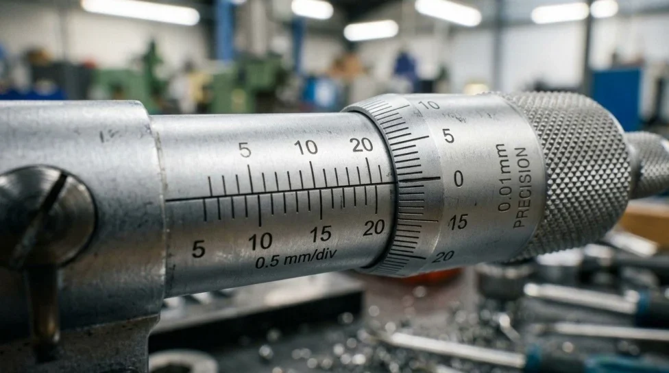
An Outside Micrometer achieves high measuring precision by utilizing a fine metric screw thread. The outside micrometer least count formula divides the spindle screw pitch by the total number of circular graduations on the rotating thimble:
- Spindle Screw Pitch: 0.50 mm (axial movement per 360-degree rotation)
- Total Thimble Divisions: 50 equal circumferential parts
- Calculated Precision: 0.50 mm / 50 = 0.01 mm (10 microns)
2. Vernier Caliper Components & Step-by-Step Measurement
Manufactured from hardened stainless steel, a Vernier Caliper is a multi-purpose tool used for checking outer dimensions, internal bore diameters, and cavity depths. Using certified precision measuring instruments for workshop tasks ensures compliance with industrial ISO standards.
2.1 Anatomy of a Vernier Caliper
- Main Beam: Holds the primary scale marked in metric divisions (mm) and imperial units (inches).
- Fixed and Movable Jaws: Hardened steel measuring faces designed for external and internal measurement.
- Depth Measuring Blade: A thin sliding strip extending from the main beam tail to measure blind hole depths.
- Locking Screw: Secures the sliding Vernier frame to maintain fixed dimensions during inspection.
2.2 Standard Reading Procedure
- Wipe measuring jaws and job surfaces using a clean, lint-free shop towel.
- Close the jaws gently and verify if the Vernier zero mark aligns with the Main Scale zero mark.
- Position the job workpiece between the measuring anvils and apply light thumb pressure on the sliding lever.
- Record the Main Scale Reading (MSR): Note the last visible millimeter line before the Vernier zero index.
- Identify the Coinciding Division (VCD): Locate the exact Vernier line aligning directly with a Main Scale line.
- Calculate final dimension: Total Reading = MSR + (VCD × 0.02 mm).
3. Outside Micrometer Construction & Solved Reading Examples
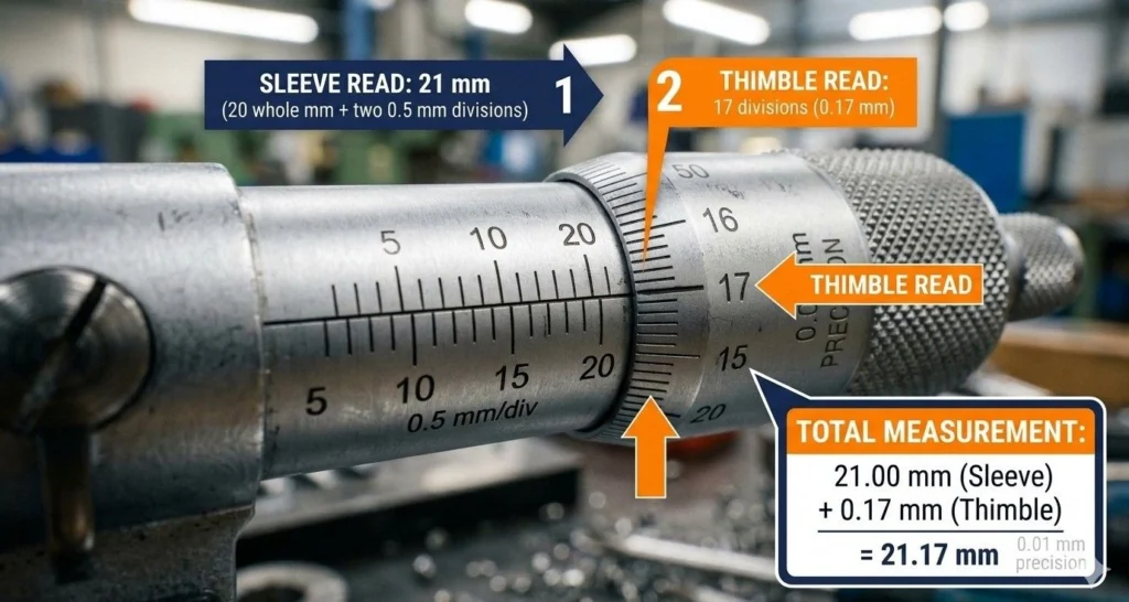
While Vernier Calipers provide versatility, an Outside Micrometer delivers superior repeat accuracy (0.01 mm) thanks to its integrated torque-limiting ratchet mechanism.
3.1 Key Structural Parts
- Drop-Forged Frame: A rigid C-frame supporting the stationary anvil and movable spindle.
- Carbide Anvil & Spindle: Wear-resistant measuring faces ground flat and parallel.
- Sleeve / Barrel: Stationary tube marked with the datum line, main millimeter graduations, and 0.5 mm subdivisions.
- Thimble & Ratchet Stop: Beveled rotating sleeve marked with 50 divisions. The ratchet stop ensures uniform measuring pressure (2 N to 5 N).
3.2 Practical Solved Reading Example
When measuring a ground shaft pin, an operator records the following sleeve and thimble readings:
- Visible Sleeve Main Division: 12.00 mm
- Visible Lower Sub-Division: 0.50 mm
- Coinciding Thimble Division: 28th line aligning with the horizontal datum line
- Thimble Fractional Value: 28 × 0.01 mm = 0.28 mm
- Final Measured Diameter: 12.00 mm + 0.50 mm + 0.28 mm = 12.78 mm
For related calculations involving shaft and hole allowances, refer to our detailed post on Limit Fit and Tolerance Standards or explore our Workshop Calculation & Science Category.
4. Positive and Negative Zero Error Correction Protocols
Zero error occurs when the instrument measuring faces touch, but the secondary scale zero mark fails to coincide with the primary reference line. Applying correct positive and negative zero error correction methods guarantees accurate job measurements.
5. Instrument Maintenance & Industrial Calibration
Precision tools require disciplined shop-floor handling to maintain calibration accuracy:
- Never force measuring anvils onto moving or rotating workpieces on lathe machines.
- Clean measuring faces with soft cloths before and after every shift.
- Avoid storing precision gauges alongside cutting tools such as files, chisels, or drill bits.
- Apply protective mineral oil before placing instruments inside velvet-lined wooden storage boxes.
- Periodically verify instrument accuracy against certified Gauge Blocks (Slip Gauges). Review guidelines on the MSDE Official Portal.
6. NIMI Pattern Mock Tests & Category Navigation
Prepare for your upcoming NCVT AITT online Computer-Based Test (CBT) by practicing interactive question sets across our main study categories:
7. Frequently Asked Questions (NCVT CBT Exam Focus)
Q1: What is the least count of a standard metric Vernier Caliper?
Ans: The standard least count is 0.02 mm (20 microns), calculated as 1 MSD (1 mm) minus 1 VSD (0.98 mm).
Q2: What is the least count of a metric Outside Micrometer?
Ans: The least count is 0.01 mm (10 microns), calculated by dividing 0.5 mm spindle pitch by 50 thimble divisions.
Q3: How is positive zero error adjusted in calculations?
Ans: Positive zero error value is subtracted from the observed reading to obtain the true component dimension.
Q4: Why is a ratchet stop essential on a micrometer?
Ans: The ratchet stop applies uniform measuring force (2 N to 5 N) across measuring faces, preventing operator pressure variations.
🚀 Ace Your NCVT AITT 2026 Online Examinations!
Practice official NIMI pattern mock tests across Trade Theory, Workshop Calculation & Science, and Employability Skills on Info ITI.