In mechanical fitting shops, sheet metal work, and precision machining, marking layout lines on metal workpieces is an essential preparation step. Scribers trace lines across layouts, but these surface marks easily rub off during handling and coolant spraying. To create permanent reference marks, machinists use high-carbon steel tools known as punches. Understanding the types of punch in marking tools, along with their specific point angles, metallurgical composition, and application rules, helps technicians ensure high accuracy during drilling, scribing, and layout operations.
This complete guide curated by Info-ITI breaks down every major punch classification, diagram specification, and workshop safety rule.
Table of Contents
Overview: What is a Punch in Workshop Practice?
A punch is a hard, pointed hand tool manufactured from High Carbon Steel (HCS) or Tool Steel. It is designed to produce small indentations or marks on metal, wood, or plastic surfaces when struck with a ball-peen hammer. In fitting, turning, and sheet metal shops, punches ensure that scribed layout lines remain visible throughout machining operations.
If you are exploring general hand tools used in fitting workshops, you can also review our guide on government ITI colleges in India to understand core curriculum requirements.
Anatomy & Components for Punches
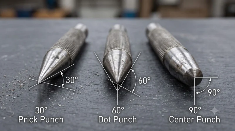
Understanding the internal structure and components for punches helps technicians choose the correct tool and maintain its working tip. A standard marking punch consists of three distinct sections:
1. Head: The flat, slightly chamfered top end that receives hammer blows. The head is kept soft or tempered to prevent mushrooming and dangerous metal splinters during impacts.
2. Body (Shank): The main hexagonal or knurled cylindrical shaft. Knurling provides a firm finger grip, preventing the punch from slipping while setting the point.
3. Point (Tip): The tapered ground conical end that penetrates the workpiece. The tip is hardened and tempered to resist dulling when striking tough alloys.
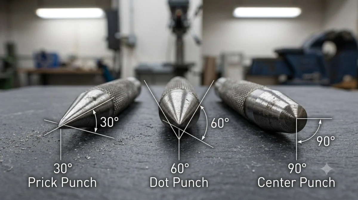
Types of Punches: Punch Angle Summary Table
When studying types of punches for technical exams or workshop operations, the primary distinguishing feature is the point angle. Review the core specifications across standard marking punches below:
| Type of Punch | Point Angle (Degrees) | Primary Purpose / Application | Indentation Shape & Depth |
|---|---|---|---|
| Prick Punch | 30° Point Angle | Locating divider points, scribing soft metals | Narrow, deep conical prick mark |
| Dot Punch | 60° Point Angle | Creating witness marks along layout lines | Medium width & depth indentation |
| Center Punch | 90° Point Angle | Seating drill bits to prevent drill wandering | Wide, shallow impression for drill tips |
| Pin Punch | Flat Flat Tip | Driving out dowel pins and rivets | Flat cylindrical contact face |
| Hollow Punch | Circular Cutting Edge | Punching clean holes in leather, rubber, gasket sheet | Hollow cylindrical cut |
1. Prick Punch: Angle, Specs & Layout Applications
A prick punch is designed for high-precision layout marking. Technicians often ask: what is the angle of a prick punch? The ground point angle on a standard prick punch is ground precisely to 30 degrees.
Key Applications & Features:
1. Locating Divider Legs: Because the prick punch point angle is sharp (30°), it forms a narrow, sharp depression. This sharp pocket allows the leg of a spring divider or trammel point to seat with extreme accuracy.
2. Soft Metal Marking: The 30° prick punch degree requires lighter hammer impacts, making it ideal for brass, aluminum, copper, and thin sheet metal layout lines without distorting the surrounding material.
3. Scribing Preparation: It provides subtle reference points along curved geometries where heavy indentations would spoil the surface finish.
2. Dot Punch: Uses, Angle & Layout Witness Marking
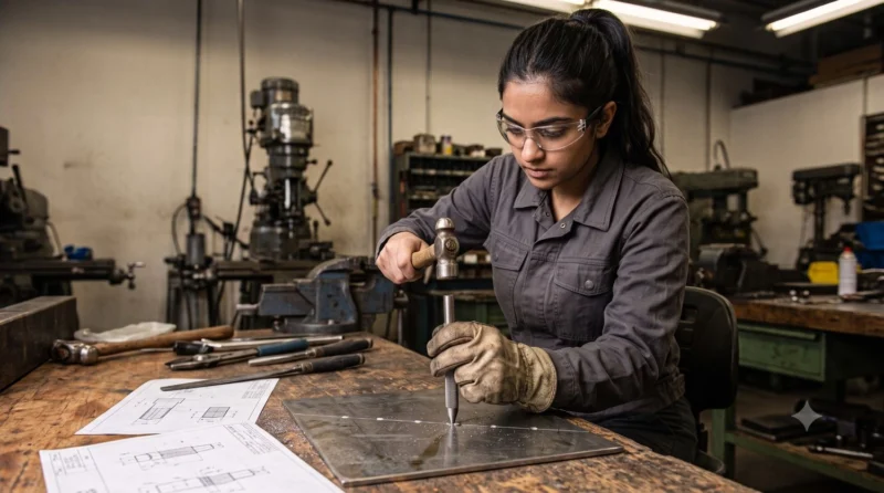
Among the various types of punch in marking tools, the dot punch tool is the most widely used hand tool for general layout visibility. The ground dot punch angle is ground to exactly 60 degrees.
Core Dot Punch Uses:
1. Witness Marking: When scribed lines are drawn on steel plates using a scriber, the lines can get wiped away during filing, machining, or coolant circulation. Technicians tap a 60° dot punch along scribed lines at regular intervals (typically 3mm to 5mm apart) to leave permanent “witness marks”.
2. Layout Permanence: Even if the surface dye or scribed line washes away, the small conical dots remain clearly visible, allowing the machinist to align cuts accurately.
3. Dot Punch Drawing & Diagram Standards: In technical drawing manuals, a dot punch diagram highlights a 60° conical tip with a knurled hexagonal body, hardened to 54–58 HRC.
3. Center Punch: Angle, Seating & Drilling Preparation
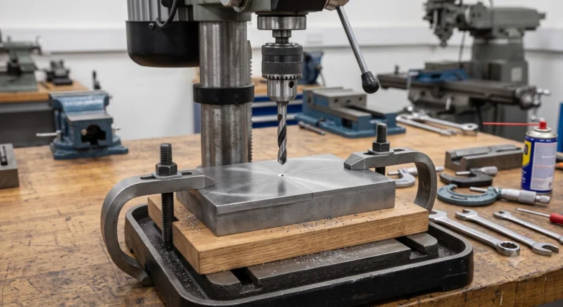
A centre punch (also spelled centre punch) features a wide point ground to a 90-degree angle. It is specifically engineered to prepare workpieces for drilling operations.
Why 90 Degrees for Center Punching?
Standard twist drill bits have a chisel edge point angle of 118 degrees (or 135 degrees for heavy-duty alloy drills). A 90° center punch angle creates a broad, wide impression that matches the entry profile of the drill point. When the rotating drill tip contacts the center mark, it seats directly without “wandering” or slipping across the workpiece surface.
Trainees practicing drill press setup and precision hole drilling should also review our guide on micrometer and vernier caliper calculations to ensure hole locations match blueprint tolerances.
4. Special Purpose Workshop Punches (Pin, Hollow, Bell & Automatic)
Beyond standard 30°, 60°, and 90° marking tools, workshops use specialized punch variations for specific fitting, assembly, and sheet metal tasks:
1. Pin Punch: Features a long, parallel cylindrical shank with a flat face (no point angle). It is used to drive out straight pins, taper pins, and cotter keys from mechanical linkages.
2. Hollow Punch: Has a hollow cylindrical body with a sharp circular outer cutting edge. Used with a wooden mallet to punch clean circular holes in gasket materials, rubber, leather, and soft plastic sheets.
3. Bell Punch: Features a spring-loaded center punch sliding inside a conical bell housing. Placing the bell over the end of a round bar automatically locates and punches the exact geometric center.
4. Automatic Center Punch: Uses an internal spring and trip mechanism to deliver a striking blow without requiring a hammer. The impact force can be adjusted by twisting the knurled top cap.
Technical Comparison: Dot Punch and Centre Punch
Understanding the functional differences between a dot punch and centre punch is a common topic in ITI NCVT exams and technical job interviews:
| Feature / Parameter | Dot Punch (60° Point) | Center Punch (90° Point) |
|---|---|---|
| Point Angle Degree | 60 Degrees | 90 Degrees |
| Impression Profile | Deeper, narrower conical dot | Wider, broader conical seating |
| Primary Function | Witness marking along scribed lines | Seating twist drill bit points |
| Hammer Blow Force | Light to medium tap | Heavy, deliberate hammer strike |
| Divider Leg Seating | Suitable for general layout lines | Too wide for precise divider positioning |
Practical Workshop Safety & Maintenance Protocol
To prevent hand injuries, damaged workpieces, and tool breakage during marking tasks, follow these essential shop-floor safety rules:
1. Inspect Punch Heads for Mushrooming: Repeated hammer impacts cause the soft head of a punch to flatten and spread into a “mushroom” shape. Always grind off mushroomed edges on a pedestal grinder before use to prevent metal fragments from flying off under hammer impact.
2. Maintain Correct Point Angles: Regrind worn tips using an oil-cooled grinding wheel. Maintain exact 30°, 60°, or 90° angles using a center gauge or angle protractor.
3. Use Ball-Peen Hammers Correctly: Select an appropriately weighted ball-peen hammer (250g to 500g) and strike the punch head squarely to avoid slipping.
4. Follow Personal Protective Guidelines: Always wear safety goggles while punching or grinding tools. Review complete workshop hazard mitigation rules in our comprehensive guide on occupational health and safety guidelines.
NIMI & NCVT Trade Theory Study Reference
Students preparing for Fitter, Turner, Machinist, or Welder trade exams can access official NIMI textbook diagrams and trade theory modules below.
📘 NIMI & NCVT Trade Theory Learning Resources
Mastering marking tool angles (30° Prick Punch, 60° Dot Punch, 90° Center Punch) is crucial for clearing NCVT AITT trade theory CBT exams and practical skill tests. Practice regularly on steel plates to develop precise hammer control.
Frequently Asked Questions (FAQs)
What is the angle of a prick punch used for dividers?
The point angle of a prick punch used for locating divider points is ground to 30 degrees.
Why is a 60-degree angle used for a dot punch?
A 60-degree point angle creates a distinct, medium-width indentation that acts as a permanent witness mark along scribed layout lines without excessively weakening the material.
What is the difference between a dot punch angle and a center punch angle?
A dot punch has a 60-degree point angle used for witness marking, whereas a center punch has a 90-degree point angle used to seat drill bits before drilling.
Final Conclusion
Understanding the various types of punch in marking tools along with their point angles (30° Prick Punch, 60° Dot Punch, 90° Center Punch) is fundamental for every machinist, fitter, and technician. Using the right punch ensures high marking accuracy, protects cutting tools, and produces professional layout work across fitting shop projects.
Preparing for ITI trade theory exams or practical skill tests? Visit the Info-ITI Homepage to access free online NIMI trade theory mock tests, study materials, and technical guides!